background image

10

SWR2100P-10G/SWR2100P-5G Owner’s Manual

Introduction

Thank you for purchasing the Yamaha SWR2100P-10G or SWR2100P-5G, an L2 switch.
This product supplies power to PoE powered devices on the network.
This owner’s manual explains how to install and set up the unit. It is intended for installers or 
facility designers.
Please be sure to read this manual before you start using the product to take full advantage of 
its features.

Please retain this manual in a safe location for future reference.

• The fanless design promotes extremely quiet operation.
• The unit can be mounted in a 19-inch rack.
• By linking the unit to the Yamaha LAN Monitor software application, you can obtain 

information about the PoE power supply status and the amount of power supplied. You can 
also stop or resume the power supply by using the software.

Please ensure that you have all of the following accessories.
• Owner’s Manual (this manual) 
• Power  Cord
• Power Cord Clamp (used only for the included dedicated power cord)
• Rubber feet (x4)

• RK-SWR Rack-mount accessory

Use this rack-mount accessory to mount the unit in a 19-inch rack. Refer to “Attaching the 
rack mount” (page 17) 
for information on how to install the unit.

• Yamaha LAN Monitor

This application software enables you to obtain information about the SWR2100P-10G/
SWR2100P-5G and to monitor an entire network, including all Dante devices on the 
network.
Download this application from the following website:
http://www.yamaha.com/proaudio/

Features

Accessories

Options

Related application software

Summary of Contents for SWR2100P-10G

Page 1: ...SWR2100P 10G SWR2100P 5G RU IT ES FR DE EN Owner s Manual Bedienungsanleitung Mode d emploi Manual de instrucciones Manuale di istruzioni Руководство пользователя English Deutsch Français Español Italiano Русский ...

Page 2: ...re does not operate normally or has been dropped UL60065_03 PRÉCAUTIONS CONCER NANT LA SÉCURITÉ 1 Lire ces instructions 2 Conserver ces instructions 3 Tenir compte de tous les avertissements 4 Suivre toutes les instructions 5 Ne pas utiliser ce produit à proximité d eau 6 Nettoyer uniquement avec un chiffon propre et sec 7 Ne pas bloquer les orifices de ventilation Installer l appareil conformémen...

Page 3: ...and if not installed and used according to the instructions found in the This applies only to products distributed by YAMAHA CORPORATION OF AMERICA class A users manual may cause interference harmful to the operation of other electronic devices Compliance with FCC regulations does not guarantee that interference will not occur in all installations If this product is found to be the source of inter...

Page 4: ...vice in an area other than in the one you purchased the included power cord may not be compatible Please check with your Yamaha dealer Check the electric plug periodically and remove any dirt or dust which may have accumulated on it When setting up the device make sure that the AC outlet you are using is easily accessible If some trouble or malfunction occurs immediately disconnect the plug from t...

Page 5: ... or remove an electric plug with wet hands Hearing loss When turning on the AC power in your audio system always turn on the power amplifier LAST to avoid hearing loss and speaker damage When turning the power off the power amplifier should be turned off FIRST for the same reason Fire warning Do not place any burning items or open flames near the device since they may cause a fire If you notice an...

Page 6: ... ventilation can result in overheating possibly causing damage to the device s or even fire If this device is to be used in a small space other than an EIA standard rack make sure that there is adequate space around the device at least 1 3 cm above Do not place the device in a location where it may come into contact with corrosive gases or salt air Doing so may result in malfunction Before moving ...

Page 7: ... device while condensation is present can cause damage If there is reason to believe that condensation might have occurred leave the device for several hours without turning on the power until the condensation has completely dried out Be sure to earth ground any static electricity from your body or clothing before touching the product Failure to observe this precaution could result in damage to th...

Page 8: ...ordance with Article 645 of the National Electrical Code and NFPA 75 The device can only be used in a fixed location such as a telecommunication centre a dedicated computer room When you install the device ensure that the protective earthing connection of the socket outlet is verified by a skilled person European models Purchaser User Information specified in EN55103 2 2009 Conforms to Environment...

Page 9: ...p panel 13 Rear panel 14 Bottom panel 15 Setting the CONFIGURATION switches 16 Attaching the rack mount 17 Connections 19 Appendix 20 Hardware specifications 20 Dimensions 21 Software license agreement 22 Particular usage in this manual The following company and product names will be abbreviated as below in this manual Yamaha L2 Switch SWR2100P 10G SWR2100P 5G This product 10BASE T 100BASE TX 1000...

Page 10: ...on you can obtain information about the PoE power supply status and the amount of power supplied You can also stop or resume the power supply by using the software Please ensure that you have all of the following accessories Owner s Manual this manual Power Cord Power Cord Clamp used only for the included dedicated power cord Rubber feet x4 RK SWR Rack mount accessory Use this rack mount accessory...

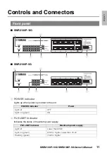
Page 11: ... power is provided to the unit 2 PoE LIMIT indicator Indicates the status of maximum power supply Front panel POWER indicator Power Light off OFF Light on green ON PoE LIMIT indicator Maximum power supply Light off Lower than 63 W Light on green 63 W or higher lower than 70 W Flashing green 70 W or higher 3 1 2 4 6 7 5 1 3 2 4 6 7 5 ...

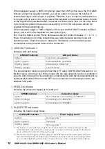
Page 12: ...anel of the main unit When turned ON the loop detection function is enabled in all ports and in the event of loop detection communication from the corresponding port is automatically blocked When turned OFF the loop detection and blocking functions are disabled in all ports 4 SPEED indicator Indicates the connection speed of the LAN port 5 PoE STATE indicator Indicates the power supply status 1 Th...

Page 13: ...0P 10G and port 5 on the SWR2100P 5G are uplink ports and do not provide a power supply function 7 CONFIGURATION switch Sets enabling disabling of functions Please refer to Setting the CONFIGURATION switches page 16 8 Product label Indicates the equipment name serial number MAC address etc of the unit Top panel 8 Serial number MAC address ...

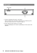
Page 14: ...Attach the included power cord clamp U shaped type For information about the attachment method please refer to Connections page 19 0 Power inlet 3 poles connector C14 type Insert the included power cord Connect to outlets between AC 100V and AC 240V 50 60 Hz Rear panel 9 0 Serial number ...

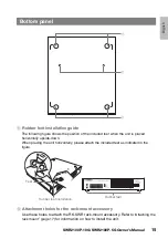
Page 15: ...horizontally upside down When placing the unit horizontally please attach the included feet as indicated in the figure B Attachment holes for the rack mount accessory Use these holes to attach the RK SWR rack mount accessory Refer to Attaching the rack mount page 17 for information on how to install the unit Bottom panel A B A Feet Rubber feet Rubber feet installation ...

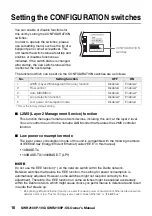
Page 16: ...umption mode of this unit is compatible with the following methods of IEEE802 3az Energy Efficient Ethernet called EEE in this manual 10BASE Te 100BASE TX 1000BASE T LPI NOTE Do not use the EEE function on the network switch within the Dante network Between switches that feature the EEE function the setting for power consumption is automatically adjusted However some switches might not respond cor...

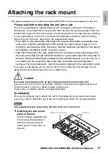
Page 17: ... keep sufficient ventilation If you cannot open the rear panel of the rack install a commercially available forced ventilation device such as a fan kit If you install a fan kit closing the rear panel may work better for heat dissipation purposes For more information refer to the owner s manual for the rack and or fan kit If you plan to relocate the unit be sure to first remove it from the rack Mov...

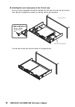
Page 18: ...Use four screws supplied with an EIA standard 19 inch rack to mount the unit into the rack Be sure to tighten the screws so that they will not get loosened You can also mount two units as shown in the figure below 19 inch rack Rack mount panel EIA standard rack Screws supplied with the 19 inch rack ...

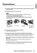
Page 19: ...icator lights up 4 Turn the power of the network devices connected to this product ON If the LINK ACT indicator corresponding to the LAN port to which the network device is connected turns green or flashes green this indicates that the status is normal If the LINK ACT indicator corresponding to the LAN port does not turn green or flash green Please check that the LAN cable is correctly connected a...

Page 20: ... of each connected powered device All ports 70W Compatible PoE powered devices PoE powered devices that comply IEEE 802 3af standards or IEEE 802 3at standards Status indicators POWER PoE LIMIT LINK ACT SPEED PoE STATE x31 POWER PoE LIMIT LINK ACT SPEED PoE STATE x16 Switches CONFIGURATION switches for modifying the settings L2MS switch Flow control switch Auto MDI MDI X switch Loop detection swit...

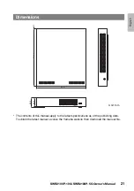
Page 21: ...G Owner s Manual 21 The contents of this manual apply to the latest specifications as of the publishing date To obtain the latest manual access the Yamaha website then download the manual file Dimensions 43 5 40 5 220 250 2 3 Unit mm ...

Page 22: ...1 3 You shall not modify remove or delete a copyright notice of YAMAHA contained in the SOFTWARE 1 4 Except as expressly provided herein no license or right express or implied is hereby conveyed or granted by YAMAHA to you for any intellectual property of YAMAHA 2 OWNERSHIP AND COPYRIGHT The SOFTWARE is protected under the copyright laws and owned by YAMAHA You agree and acknowledge that YAMAHA tr...

Page 23: ...th the provision 6 3 you shall promptly delete the SOFTWARE 6 5 Notwithstanding anything contains herein Sections 2 through 6 shall survive any termination or expiration hereof 7 SEPARABILITY In the event that any provision of this AGREEMENT is declared or found to be illegal by any court or tribunal of competent jurisdiction such provision shall be null and void with respect to the jurisdiction o...

Page 24: ...124 SWR2100P 10G SWR2100P 5G Owner s Manual ...

Page 25: ...taktierenSiebitteIhre örtliche Stadt oder Gemeindeverwaltung Ihren Abfallentsorgungsdienst oder die Verkaufsstelle der Artikel Information für geschäftliche Anwender in der Europäischen Union Wenn Sie Elektrogeräte ausrangieren möchten kontaktieren Sie bitte Ihren Händler oder Zulieferer für weitere Informationen Entsorgungsinformation für Länder außerhalb der Europäischen Union Dieses Symbol gilt...

Page 26: ...rticoli si prega di contattare le autorità locali o il rivenditore e richiedere informazioni sulla corretta modalità di smaltimento weee_eu_it_02 Información para usuarios sobre la recogida y eliminación de los equipos antiguos Este símbolo en los productos embalajes y documentos anexos significa que los productos eléctricos y electrónicos no deben mezclarse con los desperdicios domésticos normale...

Page 27: ... Greece Tel 30 210 6686168 SWEDEN FINLAND ICELAND Yamaha Music Europe GmbH Germany filial Scandinavia JA Wettergrensgata 1 400 43 Göteborg Sweden Tel 46 31 89 34 00 DENMARK Yamaha Music Denmark Fillial of Yamaha Music Europe GmbH Tyskland Generatorvej 8C ST TH 2860 Søborg Denmark Tel 45 44 92 49 00 NORWAY Yamaha Music Europe GmbH Germany Norwegian Branch Grini Næringspark 1 1332 Østerås Norway Tel...

Page 28: ...Published 03 2018 IPOE C0 2017 Yamaha Corporation Manual Development Group Yamaha Downloads https download yamaha com Yamaha Pro Audio global website https www yamaha com proaudio ...

Reviews: