SWP2 Owner’s Manual
14
Status Indicator Display
The status indicators show different things depending on
the LED mode setting.
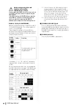
LINK/ACT setting
The status indicators show each port’s link status and
connection status.
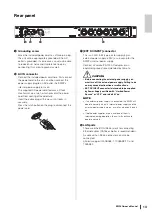
STATUS setting
The status indicators show the loop-related port’s status.
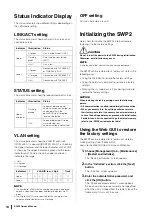
VLAN setting
The status indicators show the VLAN ID and trunk.
If DIP switch 1 is upward ([DANTE]), VLAN 1 is shown by
the upper indicator and the lower indicator unlit. VLAN 2
is shown by the upper indicator lit green and the lower
indicator unlit. Trunk is shown by upper and lower
indicators lit orange.
–: Unlit
G: Lit green
O: Lit orange
NOTE
• If a number of VLANs that cannot be completely displayed
above is specified, the upper and lower indicators are lit
green.
• If multiple VLAN IDs are specified for the same port, the
upper and lower indicators are lit orange.
OFF setting
All status indicators are unlit.
Initializing the SWP2
Here’s how to initialize the SWP2’s internal memory,
restoring it to the factory settings.
CAUTION
Do not turn off the power to the SWP2 during initialization.
Otherwise, a malfunction may occur.
NOTE
If initialization failed, contact Yamaha service personnel.
The SWP2 can be restored to its factory-set state in the
following ways.
• Using the Web GUI to restore the factory settings
• Using the cold start command to restore the factory
settings
• Entering the <I> (uppercase I) key during startup to
restore the factory settings
NOTICE
When restoring the factory settings, note the following
points.
• All communication is halted immediately after execution.
• When you execute this, the settings will also return to
their factory-set state. If necessary, use external memory
to save the settings before you proceed with initialization.
For details on how to export settings to external memory,
refer to the “SWP2 series technical data.”
Using the Web GUI to restore
the factory settings
The SWP2 can be restored to its factory-set state by
making settings from the Web GUI.
Log in to the Web GUI from Yamaha LAN Monitor.
1.
Choose [Management] tab – [Maintenance]
– [Restart and initialize].
The “Restart or Initialize” screen appears.
2.
In the “Initialize” section, click the [Next]
button.
The “Initialize” screen appears.
3.
Enter the administrative password, and
click the [OK] button.
The “Check executed content” screen appears.
Since an administrator password is not specified
when the unit is shipped from the factory, leave the
field empty if this is still the case.
Indicator
Illumination
Status
Upper
Lit green
Link is established. (LINK)
Flashing
green
Data is being transferred.
(ACT)
Unlit
Link is lost.
Lower
Lit green
Connected with 1000BASE-T
or 10GBASE-SR/LR.
Lit orange
Connected with 100BASE-TX.
Unlit
Connected with 10BASE-T.
Indicator
Illumination
Status
Upper
and lower
Flashing
orange
Loop was detected and
communication was halted, or
an abnormality in the
opticalCON light reception
level was detected.
Unlit
Loop not detected. Or loop
was detected, but
communication is not halted.
Indicators
1
VLAN ID low
high
Trunk
Upper
–
G
O
–
–
G
O
O
Lower
–
–
–
G
O
O
G
O
Summary of Contents for SWP2
Page 20: ......


