background image

English

E-

11

ADVANCED YAMAHA ACTIVE SERVO TECHNOLOGY

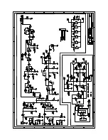
The theory of Yamaha Active Servo Technology has been
based upon two major factors, the Helmholtz resonator and
negative-impedance drive. Active Servo Processing
speakers reproduce the bass frequencies through an “air
woofer”, which is a port or opening in the speaker’s cabinet.
This opening is used instead of, and performs the functions
of, a woofer in a conventionally designed speaker system.
Thus, signals of low amplitude within the cabinet can,
according to the Helmholtz resonance theory, be outputted
from this opening as waves of great amplitude if the size of
the opening and the volume of the cabinet are in the correct
proportion to satisfy a certain ratio.
In order to accomplish this, moreover, the amplitudes within
the cabinet must be both precise and of sufficient power
because these amplitudes must overcome the “load”
presented by the air that exists within the cabinet.

Thus it is this problem that is resolved through the
employment of a new design in which the amplifier supplies
special signals. If the electrical resistance of the voice coil
could be reduced to zero, the movement of the speaker unit
would become linear with respect to signal voltage. To
accomplish this, a special negative-impedance output-drive
amplifier for subtracting output impedance of the amplifier is
used.

By employing negative-impedance drive circuits, the
amplifier is able to generate precise, low-amplitude, low-
frequency waves with superior damping characteristics.
These waves are then radiated from the cabinet opening as
high-amplitude signals. The system can, therefore, by
employing the negative-impedance output drive amplifier
and a speaker cabinet with the Helmholtz resonator,
reproduce an extremely wide range of frequencies with
amazing sound quality and less distortion.
The features described above, then, are combined to be the
fundamental structure of the conventional Yamaha Active
Servo Technology.

Our new Active Servo Technology — Advanced Yamaha
Active Servo Technology — adopted Advanced Negative
Impedance Converter (ANIC) circuits, which allows the
conventional negative impedance converter to dynamically
vary in order to select an optimum value for speaker
impedance variation. With this new ANIC circuits, Advanced
Yamaha Active Servo Technology can provide more stable
performance and improved sound pressure compared with
the conventional Yamaha Active Servo Technology, resulting
in more natural and dynamic bass reproduction.

High-amplitude
bass sound

Cabinet

Port

Air woofer
(Helmholtz resonator)

Active Servo
Processing
Amplifier

Signals

Signals of low amplitude

Advanced Negative-
impedance Converter

Summary of Contents for SW-201

Page 1: ...Subwoofer System Enceinte a Caisson de Grave SW 201 OWNER S MANUAL MODE D EMPLOI U C ...

Page 2: ...adiators stoves or other appliances that produce heat 10 Power Sources The unit should be connected to a power supply only of the type described in the operating instructions or as marked on the unit 11 Power Cord Protection Power supply cords should be routed so that they are not likely to be walked on or pinched by items placed upon or against them paying particular attention to cords at plugs c...

Page 3: ...erference with other electronic devices This equipment generates uses radio frequencies and if not installed and used according to the instructions found in the users manual may cause interference harmful to the operation of other electronic devices Compliance with FCC regulations does not guarantee that interference will not occur in all installations If this product is found to be the source of ...

Page 4: ...ing enough space above behind and on the both sides of the unit to prevent fire or damage Furthermore do not position with the rear panel facing down on the floor or other surfaces 10 Super bass frequencies reproduced by this unit may cause a turntable to generate a howling sound In such a case move this unit away from the turntable 11 Vibration generated by super bass frequencies may cause images...

Page 5: ...uality super bass sound Refer to page 11 for details on Advanced YAMAHA Active Servo Technology This super bass sound adds a more realistic theater in the home effect to your stereo system This subwoofer can be easily added to your existing audio system by connecting to either the speaker terminals or the line output pin jack terminals of the amplifier The HIGH CUT switch provides you with two pos...

Page 6: ... the ways shown in this section that is more suitable for your audio system Also refer to the owner s manual of your component to be connected to the subwoofer Left speaker Right speaker Subwoofer Amplifier Pin plug cords To AC outlet Connecting to line output pin jack terminals of the amplifier To connect with a YAMAHA DSP amplifier or AV receiver connect the SUBWOOFER or LOW PASS etc terminal on...

Page 7: ...t the amplifier has at least two sets of PRE OUT terminals If the amplifier has only one set of PRE OUT terminals do not connect the subwoofer to the PRE OUT terminals Instead connect the subwoofer to the speaker output terminals of the amplifier Refer to pages 6 and 7 When connecting to a monaural line output terminal of the amplifier connect the L MONO INPUT2 terminal When connecting to line out...

Page 8: ...onnecting to speaker output terminals of the amplifier m Using one subwoofer If your amplifier has only one set of main speaker output terminals Connect the speaker output terminals of the amplifier to the INPUT1 terminals of the subwoofer and connect the OUTPUT terminals of the subwoofer to the main speakers Left speaker Right speaker Subwoofer Amplifier Speaker output terminals To AC outlet If y...

Page 9: ...w to Connect Red positive Black negative Caution Do not let the bare speaker wires touch each other or any metal part of the subwoofer This could damage the subwoofer the amplifier or the speakers or all of them 1 Press and hold the terminal s tab as shown in the figure 2 Insert the bare wire end properly into the terminal hole Remove approx 10 mm 3 8 insulation from the speaker cord 3 Release you...

Page 10: ... it is set to LOW however you may set to HIGH if necessary Refer to Note about setting the HIGH CUT switch on page 9 Automatic power switching function When you play a source the power of the subwoofer turns on automatically by sensing audio signals input to the subwoofer On the other hand the subwoofer automatically switches to the standby mode if the source being played is stopped or the input s...

Page 11: ...nd system by using the amplifier s volume control However if you change the main speakers to others you must make this adjustment again For adjusting the VOLUME control and the HIGH CUT switch refer to Frequency characteristics on page 10 Note about setting the HIGH CUT switch This subwoofer is designed so that the optimum tone balance between the subwoofer and the main speakers is obtained when t...

Page 12: ...H CUT switch HIGH CUT LOW HIGH VOLUME 0 I0 Fig 2 shows the optimum volume level with the HIGH CUT switch at the HIGH position and the frequency characteristics when the subwoofer is combined with a typical 3 5 or 4 8 cm or 10 cm acoustic suspension 2 way system main speakers Fig 1 Fig 2 Main speaker s response 20 50 100 200 500Hz 40 50 60 70 80 90 100 HIGH CUT LOW HIGH CUT HIGH ...

Page 13: ...sh this a special negative impedance output drive amplifier for subtracting output impedance of the amplifier is used By employing negative impedance drive circuits the amplifier is able to generate precise low amplitude low frequency waves with superior damping characteristics These waves are then radiated from the cabinet opening as high amplitude signals The system can therefore by employing th...

Page 14: ...s not securely connected The VOLUME control is set to 0 Speaker cords are not connected securely Speaker cords are not connected correctly A source sound with few bass frequencies is played It is influenced by standing waves The POWER switch is set to the OFF position The AUTO STANDBY switch is set to the OFF position The level of input signal is too low The level of input signal is too low There ...

Page 15: ...N BEI HAMBURG F R OF GERMANY YAMAHA ELECTRONIQUE FRANCE S A RUE AMBROISE CROIZAT BP70 CROISSY BEAUBOURG 77312 MARNE LA VALLEE CEDEX02 FRANCE YAMAHA ELECTRONICS UK LTD YAMAHA HOUSE 200 RICKMANSWORTH ROAD WATFORD HERTS WD1 7JS ENGLAND YAMAHA SCANDINAVIA A B J A WETTERGRENS GATA 1 BOX 30053 400 43 VASTRA FRÖLUNDA SWEDEN YAMAHA MUSIC AUSTRALIA PTY LTD 17 33 MARKET ST SOUTH MELBOURNE 3205 VIC AUSTRALIA...

Reviews: