9
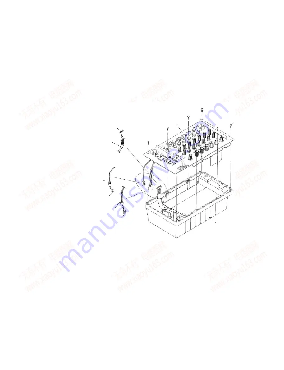
STAGEPAS 300
[340] X 8
Panel assembly
(
パネルAss'y、パネル側
)
Connector assembly A
(
束線A
)
Connector assembly B
(
束線B
)
Connector assembly C
(
束線C
)
Rear case assembly
(
リアケースAss'y、リアケース側
)
VR circuit board - CN24
(
VRシートのCN24
)
POWER circuit board - CN2
(POWER
シートのCN2
)
POWER circuit board - CN9
(POWER
シートのCN9
)
[340]: Hexagonal Tapping Screw-B (
六角ネジ B タイト
) 3.0X8 NI-BL (AAX62010)
Fig.7 (
図 7
)
8.
ミキサーAss'y(パネル側、リアケース側)
(所要時間:約 3 分)
8-1
ミキサー Ass'y を外します。(6 項参照)
8-2
[340]のネジ 8 本を外して、ミキサーAss'y からパネ
ル側とリアケース側を別けます。
(図 7)
〈パネル側の取り外し/接続時の注意〉
※
パネル側を外す時に、3 本の束線(束線 A,B,C)に
注意してください。
(図 7)
※
パネル側を取り付ける際は、3 本の束線(束線
A,B,C)を A → B → C の順に接続します。
(図 7)
《パネル側(ミキサー Ass'y)の分解》
※
以下の各部品(9 項〜 13 項)を取り外す前に、ミ
キサー Ass'y(6 項参照)
を外しておきます。
9.
INPUT シート
(所要時間:約 6 分)
9-1
パネル印刷面から[190a]の特殊六角ナット 8 個、
[200]のネジ 10 本を外します。(図 8)
9-2
VRシートのCN21、CN26のコネクターからINPUT
シートを外します。
(図 8)
※
[170]のプッシュボタン 4 個と[180]のプッシュス
ペーサ 4 個は、INPUT シートの構成部品ではあり
ません。INPUT シートを交換する際には必ずこれ
らを取り外し、新しい INPUT シートに取り付けて
ください。(図 9)
8.
Mixer Assembly (Panel Assembly, Rear
Case Assembly)
(Time required: About 3 minutes)
8-1
Remove the mixer assembly. (See procedure 6)
8-2
Remove the eight (8) screws marked [340], and
separate the panel assembly and rear case
assembly from the mixer assembly. (Fig.7) (See the
cautions below:)
<Cautions on removing panel assembly and connection>
*
When removing the panel assembly, take care
not to damage the three connector assemblies
(connector assembly A, B, C). (Fig.7)
*
When assembling the panel assembly, connect the
three connector assemblies (connector assembly
A, B, C) in alphabetical order (A
→
B
→
C). (Fig.7)
[Disassembly of Panel Assembly (Mixer Assembly)]
Before removing the following parts (in procedure 9
to procedure 13), remove the mixer assembly (see
procedure 6), rear case assembly (see procedure 8).
(Time required: About 6 minutes)
9-1
Remove the eight (8) hexagonal nuts marked [190a]
and ten (10) screws marked [200] from the panel
printing side. (Fig.8)
9-2
Remove the INPUT circuit board from the connectors
CN21 and CN26 of the VR circuit board. (Fig.8)
*
The four (4) push buttons marked [170] and four
(4) push spacers marked [180] are not parts of
the INPUT circuit board. When replacing the
INPUT circuit board, be sure to remove these
parts and attach them to the new INPUT circuit
board. (Fig.9)
www. xiaoyu163. com
QQ 376315150
9
9
2
8
9
4
2
9
8
TEL 13942296513
9
9
2
8
9
4
2
9
8
0
5
1
5
1
3
6
7
3
Q
Q
TEL 13942296513 QQ 376315150 892498299
TEL 13942296513 QQ 376315150 892498299


