For Service Engineer
Service Information
SI1705004E-00=SIGMA-G5SII Service Manual
175/273
4.15.2. Clamp Lever Change
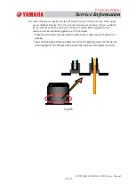
(1) Loosen the fulcrum pin fixing bolt on both sides of the clamp lever and separate the
clamp lever.
* As the clamp lever is attached to the setup stay in the specified direction,
remember the direction.
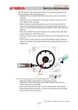
Insert the hexagon wrench from the upper
or lower side as shown in the right figure,
and loosen the upper set bolt (M3 × 1.4,
SW, FW) to pull our the fulcrum pin.
* There is no bolt hole at the center of
the fulcrum pin in the right figure.
However, actually there is a hole for
a hexagon wrench.
* For the replacement, replace the
urethane rubber and metal frame
assembly.
4.15.3. Clamp Lever Attachment
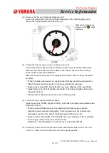
(1) Attach the clamp lever using the reverse procedure described in Item 4.15.2.
For the fixing of the clamp lever stay, there are the two knock pins each on the right
and left of the cutter unit base section, which facilitates positioning.
Slide the cutter blade assembly by hand and confirm that the clamp lever moves
smoothly.
* When the cutter blade is slid by hand, be careful not to cut your hand.
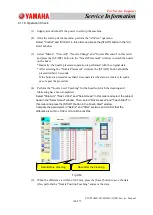
(2) Fix the tape guide cover or side cover, etc., using the screws and fix the cutter unit
onto the machine main body (Refer to Item 4.14.2, for the fixing procedure).
* Attach the silicon sheet for the tape leading so that it is placed between the clamp
levers.
Fig.D98
Fulcrum Pin


