background image

SB168-ES  Owner’s Manual

10

Controls and Functions

q

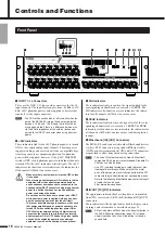
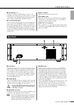
INPUT 1–16 Connectors

These are the XLR-3-31 type analog connectors for the 16 
input channels. The input level range is from -62 dBu to +10 
dBu. +48V phantom power can be supplied to devices that 
require it via the input connectors.

• The PAD will be switched on or off internally when the 

gain of the SB168-ES internal head amp is adjusted 
between -14 dB and -13 dB. Keep in mind that noise 
may be generated if there is a difference between the 
Hot and Cold impedance of the external device con-
nected to the INPUT connector when using phantom 
power.

w

+48V Indicators

These indicators light when +48V phantom power is turned 
ON for the corresponding input channels. Phantom power 
supply switching can be carried out from a compatible digi-
tal mixing console or computer application. No phantom 
power will be supplied, however, if the [+48V MASTER] 
switch is OFF, even if phantom power to individual channels 
is turned ON (the +48V indicators will still light). The +48V 
indicators also function as error indicators: the indicators for 
all channels will flash if an error occurs.

• Make sure that phantom power is turned OFF unless 

it is needed.

• When turning phantom power ON, make sure that no 

equipment other than phantom-powered devices 
such condenser microphones are connected to the 
corresponding INPUT connectors. Applying phantom 
power to a device that does not require phantom 
power can damage the device.

• Do not connect or disconnect a device to an INPUT 

while phantom power is applied. Doing so can dam-
age the connected device and/or the unit itself.

• To prevent possible damage to speakers, make sure 

that power amplifiers and/or powered speakers are 
turned OFF when switching phantom power ON or 
OFF. We also recommend setting all digital mixing 
console output controls to minimum when turning 
phantom power ON or OFF. Sudden high level peaks 
caused by the switching operation can damage 
equipment as well as the hearing of those present.

e

SIG Indicators

These indicators light green when the signal applied to the 
corresponding channel reaches or exceeds -34 dBFS. The 
SIG indicators also function as error indicators: the indica-
tors for all channels will flash if an error occurs.

r

PEAK Indicators

These indicators light red when the signal level of the corre-
sponding channel reaches or exceeds -3 dBFS. The PEAK 
indicators also function as error indicators: the indicators for 
all channels will flash if an error occurs (and during initial-
ization).

t

EtherSound [IN]/[OUT] Connectors

The SB168-ES can be connected to other EtherSound devices 
via these RJ-45 connectors using standard Ethernet cables 
(CAT5e or better recommended). [IN] and [OUT] connectors 
are provided to allow daisy chain or ring connection.

• The use of Ethernet cables with Neutrik EtherCon® 

compatible RJ-45 plugs is recommended. Standard RJ-
45 plugs can also be used.

• Use STP (shielded twisted pair) cable to prevent elec-

tromagnetic interference. Make sure that the metal 
parts of the plugs are electrically connected to the STP 
cable shield by conductive tape or comparable means.

• Refer to the following EtherSound website for the length 

of cable that can be used.
http://www.ethersound.com/

y

IN/OUT [TX]/[RX] Indicators

The appropriate indicator flashes when data is transmitted 
from (TX) or received at (RX) the EtherSound [IN]/[OUT] 
connectors. 
These indicators will also light and/or flash to display errors, 
warnings, and information as described on page 21.

• All four indicators will flash when the [Identify] button in 

the AVS-ESMonitor application (page 16) is clicked, 
and will continue to flash until the button is clicked a 
second time.

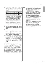
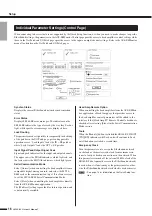
Front Panel

q

t

u

i o !0

y

!1

w e r

NOTE

CAUTION

NOTE

NOTE

Summary of Contents for SB168-ES

Page 1: ...JA ZH RU IT ES FR DE EN Owner s Manual Bedienungsanleitung Mode d emploi Manual de instrucciones Manuale di istruzioni 取扱説明書 ...

Page 2: ...two blades and a third grounding prong The wide blade or the third prong are provided for your safety If the provided plug does not fit into your outlet consult an electrician for replacement of the obsolete outlet 10 Protect the power cord from being walked on or pinched particularly at plugs convenience receptacles and the point where they exit from the apparatus 11 Only use attachments accessor...

Page 3: ...let and have the device inspected by qualified Yamaha service personnel CAUTION Always follow the basic precautions listed below to avoid the possibility of physical injury to you or others or damage to the device or other property These precautions include but are not limited to the following Remove the electric plug from the outlet when the device is not to be used for extended periods of time o...

Page 4: ...ower cord from the AC outlet the internal head amp settings are retained However if the backup battery fully discharges these settings will be lost Imminent battery depletion is indicated by the panel LEDs as described on page 21 In this case immediately save the data to a compatible digital mixer then have qualified Yamaha service personnel replace the backup battery Always turn the power off whe...

Page 5: ...nnection 12 Setup 13 About the AVS ESMonitor Software 13 Initial Setup Using the Quick Setup Function 13 Individual Parameter Settings Control Page 16 Setup Error Messages 17 Head Amp Control 18 Control from a Digital Mixing Console 18 Control From the AVS ESMonitor Application 18 Head Amplifier Parameters That Can be Monitored and Controlled 19 Troubleshooting 20 Troubleshooting 20 Messages 21 Re...

Page 6: ...panded I O Up to four SB168 ES units can be used to provide a total of 64 inputs and 32 outputs The maximum number of units that can be used may depend on the digital mixing console used Firmware Updates Two types of firmware are required firmware for the SB168 ES unit itself provided byYamaha and EtherSound firmware pro vided by AuviTran The SB168 ES firmware can be updated from a computer connec...

Page 7: ...he possi bility of heat buildup When mounting the unit in a rack with devices such as power amplifiers that generate a significant amount of heat leave more than 1U of space between the SB168 ES and other equipment Also either leave the open spaces uncovered or install appropriate ventilating panels to minimize the possibility of heat buildup To ensure sufficient airflow leave the rear of the rack...

Page 8: ...und com Latency when transferring 48 kHz signals is 5 samples 104µsec increasing by 1 4 µsec for each device added to the network including network switches EtherSound is the ideal choice for systems in which minimal latency is a priority The AVS ESMonitor software application for Windows platforms that allows setup and monitoring of devices connected to an EtherSound network is available from the...

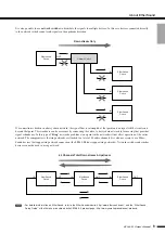
Page 9: ...ork will not affect operation of the entire network The compromise is that ring networks are limited to a total of 64 audio channels It is also necessary to use Ether Sound devices that support ring network connection the SB168 ES does support ring networks Network switches and similar devices cannot be used in a ring network For detailed information on EtherSound refer to the EtherSound website h...

Page 10: ... We also recommend setting all digital mixing console output controls to minimum when turning phantom power ON or OFF Sudden high level peaks caused by the switching operation can damage equipment as well as the hearing of those present e SIG Indicators These indicators light green when the signal applied to the corresponding channel reaches or exceeds 34 dBFS The SIG indicators also function as e...

Page 11: ...n to maximiz ing safety proper earth connection also effectively mini mizes hum and interference w AC IN Socket Connect the supplied AC power cable here First connect the AC power cable to the socket on the SB168 ES rear panel then plug it into an appropriate AC power outlet Use only the supplied AC power cable The use of an inappropriate cable can result in equipment failure overheating or even f...

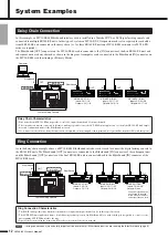
Page 12: ...haracteristics Four daisy chained SB168 ES units provide a total of 64 input channels and 32 output channels The computer can remain connected at all times making it possible to use the AVS ESMonitor application to control the SB168 ES head ampli fiers and continuously monitor the EtherSound network If a connection is broken in a daisy chain network the signal flow is interrupted at that point and...

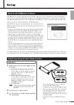
Page 13: ...he SB168 ES units are changed or the connected devices SB168 ES MY16 ES64 are replaced it will be necessary to perform the Quick Setup operation again The Quick Setup function cannot be used when EtherSound cards from other manufacturers are used In such a case the neces sary initial parameters must be set up manually refer to Individual Parameter Settings Control Page on page 16 for details 1 Det...

Page 14: ... If you selected option B in step 1 connect the dig ital mixing console s REMOTE connector to the MY16 ES64 card HA REMOTE connector via a 9 pin D sub cross cable 9 Turn the power to all devices ON 10 Select the word clock master on the digital mix ing console For a daisy chain network select either INT48K or INT44 1K and for a ring network select the 1 2 channel of the slot in which the MY16 ES64...

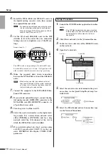
Page 15: ...in Setup ID 1 as follows 1 16 17 32 33 48 49 64 The MY16 ES64 output channels are assigned to the SB168 ES outputs in the same way 1 8 9 16 17 24 25 32 In a ring network the input and output channels are assigned in sequence from the first to last SB168 ES unit within the maximum 64 channel limitation according to the number of SB168 ES units used and the Channel Allocation setting As long as the ...

Page 16: ...t Unicast when controlling the head amplifiers from a compatible digital mixing console and select the MY16 ES64 card as the communication target It is also necessary to set the MY16 ES64 Serial Communication Mode Select Slave when controlling the head amplifiers directly from the AVS ESMonitor application The Multicast setting is provided for future expansion and is not currently available Head A...

Page 17: ...ation is not supported by the Quick Setup function The IN OUT TX RX indicators of the MY16 ES64 card will flash while this error message is dis played Redo the connections so that the MY16 ES64 functions as Primary Master Setup ID of all SB168 ES is not assigned The Setup ID has not been set for any of the SB168 ES units on the EtherSound net work The Setup ID for at least one unit must be set The...

Page 18: ...tions The AVS ESMonitor application can be used both to set EtherSound parameters and control the SB168 ES head amplifiers To control the head amplifiers from the AVS ESMonitor application either select AVS ESMonitor in the Quick Setup Head Amp Controller field or perform the setup procedure described below and a Head Amp page will be added to the AVS ESMonitor interface 1 Select the SB168 ES to b...

Page 19: ... port to the system The on screen head amplifier controls can be operated both by click and drag and via the mouse scroll wheel Sound output may be briefly interrupted when adjusting gain but this is normal Since the gain is being internally adjusted in 6 dB steps output is briefly muted to prevent noise The following parameters are not supported and cannot be edited even if shown on the display D...

Page 20: ... function Did you change any patch settings via the AVS ESMonitor application after executing the Quick Setup function Are the AVS ESMonitor patch settings appropriate Net Patch or I O Patch page Is output muted at the digital mixing console An error message is displayed during Quick Setup Refer to page 17 for information on error messages that might be displayed during execution of the AVS ESMoni...

Page 21: ...st and the unit will be initialized Stop using the unit as quickly as possible and contact your Yamaha dealer Low Battery The backup battery is beginning to run low Memory Error All Memories were Initialized The internal backup memory was corrupted and all data has been initialized If the error reoccurs after restarting the unit there is a possibility that the backup battery has been depleted Cont...

Page 22: ...e device is operating with the DIP switches set to initialization or some other special mode To resume normal operation turn the power OFF set DIP switches 5 8 to their up positions then turn the power ON again Information Indicators AVS ESMonitor Error Status Details Solution HA Remote Communication Error Rx Buffer Full Too much data has been received at the HA Remote input port If any of these e...

Page 23: ...ds on each cable specification Control I O Characteristics A CAT5e STP Shielded Twisted Pair cable is recommended Maximum length is 100 m Power Requirements US Canada 120V 65W 60Hz Korea 220V 65W 60Hz China 220V 65W 50Hz Japan 100V 65W 50 60Hz Other 110V 240V 65W 50 60Hz Dimensions 480 x 350 x 132 mm W x D x H Net Weight 8 kg Temperature Range Operation free air 0 C to 40 C Storage 20 C to 60 C AC...

Page 24: ...ncy Input Output RL Conditions Min Typ Max Unit INPUT 1 16 OUTPUT 1 8 600 Ω GAIN 10dB 1 5 0 0 5 dB Input Output RL Conditions Min Typ Max Unit INPUT 1 16 OUTPUT 1 8 600 Ω Input level 62 dBu GAIN 62dB Output level 4 0 dBu Typ 2 0 2 dB Input level 10 dBu GAIN 10dB Output level 4 0 dBu Typ 2 0 2 Input Output RL Conditions Min Typ Max Unit INPUT 1 16 OUTPUT 1 8 600 Ω 4 dBu 20 Hz 20 kHz GAIN 62dB 0 1 4...

Page 25: ...A Remote Connection M7CL 48 3 48in 24out D sub 9pin M7CL 32 3 48in 24out D sub 9pin LS9 32 2 32in 16out via MY Card Slot LS9 16 1 16in 8out via MY Card Slot DM1000 2 32in 16out D sub 9pin DM2000 4 64in 32out D sub 9pin PM5D PM5D RH 4 64in 32out D sub 9pin DME64N 4 64in 32out D sub 9pin DME24N 1 16in 8out D sub 9pin DME8i ES 8o ES 4io ES 4 64in 32out Not supported 02R96 4 64in 32out Not supported 0...

Page 26: ...SB168 ES Owner s Manual 170 MEMO ...

Page 27: ...SB168 ES Owner s Manual 171 MEMO ...

Page 28: ...rogeräte kontaktieren Sie bitte Ihre örtliche Stadt oder Gemeindeverwaltung Ihren Abfallentsorgungsdienst oder die Verkaufsstelle der Artikel Information für geschäftliche Anwender in der Europäischen Union Wenn Sie Elektrogeräte ausrangieren möchten kontaktieren Sie bitte Ihren Händler oder Zulieferer für weitere Infor mationen Entsorgungsinformation für Länder außerhalb der Europäischen Union Di...

Page 29: ...or contacte a sus autoridades locales y pregunte por el método correcto de disposición ES Informazioni per gli utenti sulla raccolta e lo smaltimento di vecchia attrezzatura Questo simbolo sui prodotti sull imballaggio e o sui documenti che li accompagnano significa che i prodotti elettriche e elettroniche non dovrebbero essere mischiati con i rifiuti domestici generici Per il trattamento recupero...

Page 30: ...ct MUST be used Follow all installation instructions Failure to follow instruc tions could void your FCC authorization to use this product in the USA 3 NOTE This product has been tested and found to comply with the requirements listed in FCC Regulations Part 15 for Class B digital devices Compliance with these require ments provides a reasonable level of assurance that your use of this product in ...

Page 31: ...a S A Ctra de la Coruna km 17 200 28230 Las Rozas Madrid Spain Tel 91 639 8888 SWEDEN Yamaha Scandinavia AB J A Wettergrens Gata 1 Box 30053 S 400 43 Göteborg Sweden Tel 031 89 34 00 DENMARK YS Copenhagen Liaison Office Generatorvej 6A DK 2730 Herlev Denmark Tel 44 92 49 00 NORWAY Norsk filial av Yamaha Scandinavia AB Grini Næringspark 1 N 1345 Østerås Norway Tel 67 16 77 70 RUSSIA Yamaha Music Ru...

Page 32: ... Musical Instrument Division Yamaha Corporation 2008 Yamaha Corporation WP93760 901PODHX X 03C0 Printed in Japan Yamaha Pro Audio global web site http www yamahaproaudio com Yamaha Manual Library http www yamaha co jp manual ...

Reviews: