background image

RM1x SEQUENCE REMIXER   

87

PA

TTERN MODE

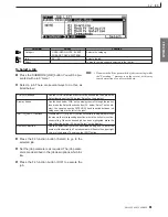
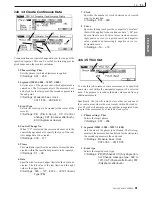
tracted from) the velocities within the segment, begin-
ning with a “0” amount at the beginning of the seg-
ment, and ending with the full Range amount at the end
of the segment.

Velocity cannot be less than 1 or higher than 127. Ad-
justed valves below 1 are raised to 1, adjusted values
above 127 are set to 127.

Settings : -127  ... 0 ... +127

Original velocities

Range = +50 (M: 001:1 ~ 003:1)

(Vel)

64

64

64

64

64

64

64

74

84

94

114

104

64

54

44

34

14

21

Range =  –50 (M: 001:1 ~ 003:1)

(Vel)

(Vel)

Job 05 Transpose

1

3

2

4

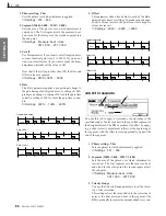
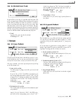
You use this job to tranpose a specified range of notes (pitches)
in a specified segment of the designated track. You set the
transposition level in semitone increments.

1. Phrase setting:  Phrs

Sets the phrase to which adjustment is applied.

Settings : 001 ... 256

2. Segment (M001:1:000 ~ M257: 1:000)

Sets the area of the phrase over which adjustment is
carried out. The first segment sets the measure, beat,
and clock for the start point; the second segment sets
the end point.

Settings : Measure: beat : clock

001:1:000 ... 257:1:000

3. Note range (Note = C-2~G8)

Sets the note range to be transposed.

Settings : C-2 ... G8

4. Transpose

The Transpose value sets the number of transposition
intervals (semitones). A value of +12 would transpose
all targeted notes up by exactly one octave, while a value
of -12 would transpose down by an octave.

Settings : -127 ... +000 ... +127

Job 06 Glide

1

3

2

4

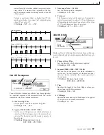
Replaces all notes following the first note in the specified seg-
ment with pitch bend data, producing smooth glides from note
to note.

1. Phrase setting:  Phrs

Sets the phrase to which adjustment is applied.

Settings : 001 ... 256

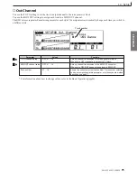
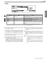
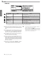
2. Segment (M001:1:000 ~ M257: 1:000)

Sets the area of the phrase over which adjustment is
carried out. The first segment sets the measure, beat,
and clock for the start point; the second segment sets
the end point.

Settings : Measure: beat : clock

001:1:000 ... 257:1:000

3. Time

Specifies the length of the glide. Higher values pro-
duce a longer glide between notes.

Settings : 000 ... 100

4. PB Range

Specifies the maximum pitch bend range to be applied
by the glide job in semitone increments.

Settings : 01 ... 24

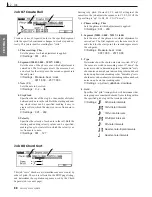
12. Job
Summary of Contents for RM1x

Page 1: ......

Page 2: ... interference relocate reorient the antenna If the antenna lead in is 300 ohm ribbon lead change the lead in to co axial type cable If these corrective measures do not produce satisfactory results please contact the local retailer authorized to distribute this type of product If you can not locate the appropriate retailer please contactYamaha Corporation of America Electronic Service Division 6600...

Page 3: ... function or effect works when the unit is operating as designed are not covered by the manufacturer s warranty and are therefore the owners responsibility Please study this manual carefully and consult your dealer before requesting service ENVIRONMENTAL ISSUES Yamaha strives to produce products that are both user safe and environmentally friendly We sincerely believe that our products and the pro...

Page 4: ...ng the instrument or during electrical storms Before connecting the instrument to other electronic components turn off the power for all components Before turning the power on or off for all components set all volume levels to minimum Do not expose the instrument to excessive dust or vibrations or extreme cold or heat such as in direct sunlight near a heater or in a car during the day to prevent t...

Page 5: ...or artists with a DJ background while in depth sequencing and editing functions make it possible to create sophisticated original patterns and songs from scratch In addition to powerful sequence recording and playback capability the RM1x also features a great sounding tone generator built in so you don t need any extra equipment You can even edit the voices to create sounds that are perfectly suit...

Page 6: ...s to be accessed and edited when you need to be in total control of your sound Powerful sequencing capabilities with in depth editing function make it possible to create even complex patterns and musical textures Assemble grooves in real time in the Pattern mode each of the Pattern mode s styles has up to 16 sections which can be directly switched in real time during playback via the RM1x key boar...

Page 7: ... chapter 2 Pattern mode Some of the overlapping explanation in chapter 3 Pattern Chain mode and chapter 4 Song mode is omitted In such cases the appropriate page of chapter 2 Pattern mode is indicated so that you can refer to it List Book This is a booklet that contains various lists such as the Voice list Preset Style list Effect list MIDI data format and MIDI implementation chart Printing conven...

Page 8: ...ch button and control and read about their function Quickstart Guide page20 This brief easy to follow section shows you how to use the basic features and functions of your new RM1x Function tree page 32 This lets you locate the desired information within the structure of the command hierarchy Glossary page 146 This section contains unfamiliar terms or phrases in alphabetical order with their expla...

Page 9: ...S 1 Function tree 32 2 How the RM1x is organized 34 3 Sequencer block 35 4 Tone generator block 37 5 Controller block 38 6 Effect block 39 7 About floppy disks 42 Chapter 2 PATTERN MODE 1 PATTERN Playback 46 2 Recording 49 3 Groove 55 4 Play FX 57 5 MIDI delay 60 6 Arpeggio 62 7 Voice 63 8 Voice Edit 65 9 Effect 69 10 Setup 73 11 Disk 76 12 Job 80 13 Edit 99 14 Split 108 Chapter 3 PATTERN CHAIN MO...

Page 10: ...rn 129 Chapter 5 UTILITY MODE 1 System 132 2 MIDI Setup 135 3 MIDI Filter 137 Appendix 1 Specifications 140 2 Troubleshooting 142 3 Error Messages 144 4 Glossary 146 5 Index 150 The illustrations and LCD screens as shown in this owner s manual are for instructional purposes only and may be different from the ones on your RM1x ...

Page 11: ...ear panel MIDI IN connector red MIDI IN indicator or when MIDI data is transmitted by the RM1x via the MIDI OUT connector green MIDI OUT indicator 3 LCD Display The RM1x s large backlit LCD display panel displays the parameters and values related to the currently selected operation or mode The Display Knobs page 12 and Function Buttons located immediately below the LCD display directly affect the ...

Page 12: ... assigned to both the A and B groups via the KNOB ASSIGN function mentioned above 8 Cursor Buttons The cursor buttons move the cursor around the LCD display screen highlighting the various parameters that are available for editing the RM1x cursor appears as a dark block with inverse characters 9 NO 1 and YES 1 Buttons The NO 1 and YES 1 buttons are used to edit change the value of the parameter at...

Page 13: ...o performs a range of functions as specified by the keyboard mode button below track selection transposition numeric data entry track mute solo and section selection The black keys also perform a range of other functions such as selecting specific track ranges and memorizing a number of track mute setups 15 Keyboard Mode Buttons These buttons modify the function of the RM1x keyboard for track sele...

Page 14: ...required via the UTILITY mode page 137 The MIDI OUT connector can be connected to an external tone generator or synthesizer if you want to drive external voices from the RM1x sequencer Like the MIDI IN connector MIDI filters can be set for the MIDI OUT connector via the UTILITY mode 5 L MONO R OUTPUT Jacks These are the main stereo outputs from the RM1x tone generator system see Audio equipment co...

Page 15: ...loppy disk Disks must be inserted or removed gently and firmly and only while the access indicator is dark 1 Floppy disk slot 2 Disk in use indicator 3 Eject button n The back of a floppy disk contains a write protect tab as shown in the following illustration When this tab is in the downward position with the window open it will not be possible to modify add or delete data When you wish to protec...

Page 16: ... adaptor around the cable clip as shown below to prevent accidental unplugging of the cable during operation 2 Plug the AC adaptor into an AC outlet and turn on the RM1x STANDBY ON switch When turning the power off simply reverse the procedure WARNING Use only the included PA 5C AC adaptor or other adaptor specifically recommended by Yamaha Using other AC adaptors will cause malfunctions Also be s...

Page 17: ...10 20 40 60 17 18 19 20 21 22 23 24 10 34 60 16 GAIN 10 34 60 16 GAIN 10 34 60 16 GAIN 10 34 60 16 GAIN 10 34 60 16 GAIN 10 34 60 16 GAIN 10 34 60 16 GAIN 10 34 60 16 GAIN 10 34 60 16 GAIN 10 34 60 16 GAIN 10 34 60 16 20 10 10 0 10 0 GAIN 20 10 GAIN 10 34 60 16 GAIN OFF ON FADER MODE 24 10dBV UNBAL Audio equipment connections To output the sound of the RM1x connect an amp or mixer to the output ja...

Page 18: ...Realtime recording input will be easier if you use a MIDI keyboard Use a MIDI cable to connect the MIDI OUT of the external MIDI keyboard to the MIDI IN connector on the rear panel MIDI OUT Connecting a tone generator module RM1x song and pattern playback data can be used to play an external tone generator module Use a MIDI cable to connect the MIDI OUT connector on the rear panel to the MIDI IN c...

Page 19: ...o connect the MIDI OUT connector of the RM1x to the MIDI IN connector of the MTR and the MIDI IN connector of the RM1x to the MIDI OUT connector of the MTR If you use MTC or MMC to control an MTR set the Utility mode MIDI page MIDI Sync setting to MTC MTR MTC MMC compatible MIDI OUT MIDI IN MTR MTC MMC compatible MIDI IN MIDI OUT Synchronizing the RM1x by MTC from an external device Controlling an...

Page 20: ... transposition Higher or lower keys indicate transposition by the corresponding number of semitones in the corresponding direction The amount of trans position is also indicated by the TRANS parameter in the display More on transposition on page 27 1 Select a Style Use Display Knob 1 to select a preset style P01 P60 2 Start Playback Press the PLAY p button The currently selected section of the sel...

Page 21: ... the various sections each contains Press the STOP s button to stop playback when done SETUP 7 Use the Real time Controller Knobs Try rotating the RM1x controller knobs to hear their effect The default parameters are labeled below each knob The KNOB button selects the A or B parameter group The knobs affect the currently selected track You can quickly select any of the 16 tracks by pressing the ap...

Page 22: ...py disk slot Insert the disk all the way until it clicks into place 2 Press the SONG button You will enter Song mode 3 Press the DISK button You will enter Disk submode 4 Press the DISK button again You will enter Load page and the top line of the display will indicate SONG DISK 2 Load 5 Use the CURSOR button to move the cursor to the file you wish to play 6 Press the F1 button LOAD to start the l...

Page 23: ...ng the corresponding MODE button PATTERN PATT CHAIN SONG or UTILITY The corresponding indicator will light and the name of the selected mode will appear in the upper left hand corner of the LCD Display Here s a brief summary of what the modes do and page references to the related sections in this manual Mode Description PATTERN This is the RM1x mode you ll probably use for most recording and playb...

Page 24: ...ure can be used to create simple automatic arpeggios based on notes played on the RM1x keyboard VOICE The VOICE submode allows any of the RM1x s voices to be assigned to individual tracks and includes volume pan and effect send controls for each track VOICE EDIT This submode provides access to in depth voice editing parameters that you can use to customize voices for your own sound EFFECT Detailed...

Page 25: ... right corner of the display Then press the ENTER but ton In all of the RM1x displays the currently selected parameter or function is indicated by a cursor which can be either an inverse block i e the selected value will appear as white char acters in a black block or the opposite if the NEGA mode is selected via the UTILITY mode LCD MODE function page 133 or an underline The underline type cursor...

Page 26: ...ted display can be accessed via the display knobs they will ap pear directly above the knobs as shown in the example below To adjust a knob related parameter simply rotate the knob either clockwise to increase the value or counter clockwise to decrease the value For more rapid adjustment when for example you need to quickly cover a large value range rotate the appropriate display knob while holdin...

Page 27: ...board key corresponding to the currently selected track will flash While still holding the TRACK button simply press the key corresponding to the track you want to select the corresponding indicator will flash and the selected track will be highlighted on the LCD Display then release the TRACK button TRANSPOSE This mode provides a fast easy way to transpose playback pitch in semitone increments fr...

Page 28: ...isengaged when the MUTE mode is disengaged To solo a track press the MUTE button while holding the SHIFT button The MUTE button indicator will flash at a faster rate than when the MUTE mode is engaged and the indicator above the cur rently soloed track will flash Simply press a different key to solo a different track then press the MUTE button a second time the MUTE button indicator will go out to...

Page 29: ...es the data to its previous condition Redo is a function that cancels the Undo operation and re executes the operation These jobs are very convenient when important data has been damaged because of recording editing or a job These jobs can be used for recording editing and job except Name op erations in the Pattern mode Pattern chain mode and the Song mode and for Patch operations in the Pattern m...

Page 30: ...ed track Selects the BPM track in the SONG mode Moves the cursor to successively lower track numbers Moves the cursor to successively higher track numbers Moves the cursor to tracks in the corresponding directions While holding the TRACK and ALL buttons simultaneously the effect of the Knobs will be applied to all tracks While holding the TRACK and 1 8 buttons simultaneously the effect of the Knob...

Page 31: ...ains the basic concepts that you need to know before use such as the mode structure and the internal structure of the RM1x 1 Function tree 32 2 How the RM1x is organized 34 3 Sequencer block 35 4 Tone generator block 37 5 Controller block 38 6 Effect block 39 7 About floppy disks 42 ...

Page 32: ...page 89 Job11 Copy Event page 89 Job12 Erase Event page 90 Job13 Extract Event page 90 Job14 Create Continuous Data page 91 Job15 Thin Out page 91 Job16 Modify Control Data page 92 Job17 Time Stretch page 92 Phrase Job18 Copy Phrase page 92 Job19 Exchange Phrase page 93 Job20 Mix Phrase page 93 Job21 Append Phrase page 93 Job22 Split Phrase page 94 Job23 Get Phrase page 94 Job24 Put Phrase page 95...

Page 33: ...ll page 125 Job08 Chord Sort page 125 Job09 Chord Separate page 125 Event Job10 Shift Clock page 125 Job11 Copy Event page 125 Job12 Erase Event page 126 Job13 Extract Event page 126 Job14 Create Continuous Data page 126 Job15 Thin Out page 126 Job16 Modify Control Data page 126 Job17 Time Stretch page 126 Measure Job18 Create Measure page 126 Job19 Delete Measure page 126 Track Job20 Copy Track p...

Page 34: ...erator block page 37 Controller block page 38 Effect block page 39 Arpeggio block page 62 How the blocks are connected The five blocks are connected as follows 2 How the RM1x is organized Audio signals MIDI messages Audio signals Tone Generator block Effect block Sequencer block MIDI IN MIDI OUT External MIDI device MIDI tone generator External MIDI device MIDI keyboard MIDI messages Phrase Patter...

Page 35: ...single instrument patterns combine two or more phrases to create a single backing pattern Patterns are created in the Pattern mode page 45 The RM1x manages patterns by Style by Section and by phrase The RM1x provides 60 x 16 960 patterns Style Styles are groups of 16 patterns or sections see Sec tion below which can be selected at any time and in any order during playback in the RM1x PATTERN mode ...

Page 36: ...as memory for 20 Pattern Chains 3 Sequencer block Songs Songs are songs that have been created by recording musi cal data to tracks in the Song mode The RM1x s song memory can hold 20 songs Track structure of a song Each song consists of 16 sequence tracks and one BPM tempo track The sequence tracks are used to record musical data Data can be recorded from the controller block etc using realtime r...

Page 37: ... tone generator block The tone generator block is what actually produces sound in response to the MIDI messages received from the sequencer block the controller block and from the MIDI IN connector This is a 16part 32note polyphonic multi timbral tone genera tor Voices Voices are the individual sound programs that you can edit which are used by the tone generator to produce sound There are two typ...

Page 38: ...annel setting of the keyboard track either to one of the parts of the tone generator or to the MIDI OUT connector Relationship to other blocks In Pattern mode Pattern Chain mode and Song mode the con troller block is connected to the various parts of the tone gen erator and to the MIDI OUT connector via the keyboard track recording track of the sequencer block Data from the controller block passes...

Page 39: ...cious ness and depth to the sound In Effect submode you can select one of 11 Effect Types and modify parameter values to adjust the character of the chorus Effect submode settings are remembered independ ently for each style song Variation effect The variation effect provides 43 types of effect including reverb and chorus and also distortion and overdrive etc In Effect submode you can select one o...

Page 40: ...Pan pages 71 121 A bus line called Send Chorus To Reverb pages 71 121 con nects the chorus effect to the reverb effect By using this bus line you can connect the chorus effect and reverb effect in series 6 Effect block How the effects work Variation Insertion When Variation connection is set to Insertion the three effects will be connected as shown in the diagram below Of the 16 parts of the tone ...

Page 41: ...ts will be sent to the reverb effect chorus effect and variation effect ac cording to the Voice submode settings Reverb Send Level pages 64 120 Chorus Send Level pages 64 120 and Variation Send Level pages 64 120 Here you can adjust the effect depth for each part The stereo location of the effect output is determined by the Effect submode settings Reverb Pan pages 72 121 Chorus Pan pages 71 121 an...

Page 42: ...from the drive Press the eject button firmly and accurately and make sure that the disk is ejected If the disk catches inside and does not slide out smoothly firmly press the eject button once again or re insert the floppy disk and then press the eject button once again While the disk in use indicator is lit data is being transferred between the floppy disk and the RM1x While the disk in use indic...

Page 43: ...e submode settings Effect submode settings SMF SMF Standard MIDI File is defined as a suggested format for MIDI musical data and is a sequencer data format used by many musical instrument manufacturers and computer software companies Devices that are Standard MIDI File compatible can exchange sequence data via floppy disk etc SMF handles one Song or one Section style as a single file Play FX Out C...

Page 44: ...44 RM1x SEQUENCE REMIXER BASIC CONCEPT MEMO ...

Page 45: ...of dance and contemporary music The PATTERN mode lets you record up to 50 original user styles which can be used in the same way as the preset styles This chapter explains all the PATTERN mode operations 1 PATTERN Playback 46 2 Recording 49 3 Groove 55 4 Play FX 57 5 MIDI delay 60 6 Arpeggio 62 7 Voice 63 8 Voice Edit 65 9 Effect 69 10 Setup 73 11 Disk 76 12 Job 80 13 Edit 99 14 Split 108 ...

Page 46: ...pattern playback Track number 01 16 Shows the current selected track number Track number selection can be accomplished via this parameter or by the keyboard method described on page 27 Transpose 36 36 Shows the current transpose value Transposition can be accom plished via this parameter or by the keyboard method described on page 27 Measure Sets playback start location or shows current playback l...

Page 47: ...k Track number 01 16 Shows the current selected track number Track number selection can be accomplished via this parameter or by the keyboard method described on page 27 Transpose 36 36 Shows the current transpose value Transposition can be accom plished via this parameter or by the keyboard method described on page 27 Measure Sets playback start location or shows current playback location Length ...

Page 48: ...ng the phrase names in the PATCH mode display indicates whether the length of the phrase is less than or equal to that of the pattern or whether it is longer than that of the pattern Phrase length less than or equal to pattern length Phrase length greater than pattern length 1 PATTERN Playback ...

Page 49: ...to engage the record standby mode The red REC e button indicator will light and the PATTERN mode display will appear as shown below 6 Use display knob 2 to select the record mode you in tend to use REPL REPLACE OVER OVERDUB STEP STEP and GRID GRID At this point you can also use display knob 1 to determine whether the pattern will loop or not during recording Time signature Track number Track statu...

Page 50: ...spose value Transposition can be accom plished via this parameter or by the keyboard method described on page 27 Measure Sets recording start location or shows current recording location Length 001 256 Indicates phrase length in measures Time Signature 1 16 16 16 1 8 16 8 1 4 8 4 Indicates the pattern s time signature Track status M S Indicates track SOLO or track MUTE The highlighted track number...

Page 51: ...3 Press the PLAY p button to begin recording The metronome will sound and you ll be given a one measure count in prior to the first measure actually recorded The count in is also indicated by negative numbers in the MEAS parameter Play the required part either on the RM1x keyboard or via an external MIDI keyboard 4 Press the STOP s button when you re ready to stop recording The normal PATTERN play...

Page 52: ... ENTER button to actually enter the specified value Gate time 001 200 The length of the entered note Used to produce legato staccato and other effects Rest Enters a rest of the currently selected note length at the note pointer position Tie Lengthens the previously entered note by tying another note of the same length and pitch to it Delete Deletes the note or chord at the note pointer BkDelete Mo...

Page 53: ...hat you want to delete You will actually hear the appropriate note or chord when the note pointer is moved to an exist ing note symbol When you move the note pointer past the end of the note display the next measure will appear If you move past the last measure in the phrase the first measure of the phrase will appear 2 Recording The Numeric POINTER Display The POINTER area of the step record disp...

Page 54: ...by the key LEDs Chords can be entered simply by entering another note with a different pitch at the same location If an odd time signature such as 5 4 is specified the OCT DOWN and OCT UP buttons can be used to shift the grid so that the extra note positions can be accessed During GRID recording you can press the PLAYp button to start playback and monitor the material be ing recorded 5 Repeat step...

Page 55: ...to a 16th note location in the 1 measure groove 3 Groove Pressing the same key toggles the corresponding note position on and off You can also select a single note position and de select all others at the same time by pressing a white key while holding the SHIFT button 5 Adjust the groove parameters as required for the se lected note positions using the NOTE OFFSET CLOCK SHIFT GATE OFFSET and VELO...

Page 56: ...Pattern play back mode 3 Press the REC e button to engage the record standby mode 4 Set the REC TYPE parameter to OVERDUB 5 Press the PLAY p button to begin recording You don t actually need to record any new data the grid groove setting will automatically be recorded 6 Press the STOP s button to stop recording after the pattern has played through once The Grid Groove settings will automatically b...

Page 57: ...ation to create deliberate out of phase effects octave harmony and the addition of 2 parallel harmony lines The Harmonize settings will be individually retained in memory for each user style but when applied to a preset style the Harmonize settings will be lost as soon as a different style is selected Track number Transpose Parameter Values Function Unison OFF x2 x8 Specifies the number of unison ...

Page 58: ...to the original velocities See below for detail Track number 01 16 Shows the current selected track number Track number selection can be accomplished via this parameter or by the keyboard method described on page 27 Transpose 36 36 Shows the current transpose value Transposition can be accom plished via this parameter or by the keyboard method described on page 27 25 33 50 66 75 100 125 150 200 30...

Page 59: ...You use this parameter to apply an offset to the track s velocity values Positive values increase the playback velocity while nega tive values decrease it Original data VELOCITY OFFSET 20 Vel 96 64 32 127 96 VELOCITY OFFSET 20 Vel 116 84 52 127 116 Vel 76 44 12 107 76 Recording the PLAY FX Settings The grid groove settings can actually be merged into the se quence data as follows 1 Make the PLAY F...

Page 60: ...o MIDI clocks 480 clocks per quarter note thus a setting of 120 produces a 16th note delay a setting of 240 produces a 8th note delay etc Delay level 000 127 Specifies the level volume of the delay sound as a percentage The higher the value the louder the delay sound Repeat times 00 64 Sets the number of delay repeats A setting 3 for example produces 3 repeats Track number 01 16 Shows the current ...

Page 61: ...ile negative val ues produce decreasing repeat level Feedback note 24 00 24 RND Offsets the pitch of the delayed notes so that each repeat will have a different pitch By setting an appropriate FB NOTE value it is pos sible to produce delays that sound like glissandos or even arpeg gios Each increment corresponds to a semitone The RND setting produces delay repeats with random pitch Feedback gate t...

Page 62: ...he selected arpeggio TYPE above Hold ON OFF Determines whether the arpeggio will continue to play when the notes are released or not When this parameter is ON the arpeggio will continue to play when the notes played on the RM1x keyboard or an external keyboard are released When OFF the arpeggio will stop as soon as the notes are released Octave range 1 4 Specifies the range of octaves the arpeggio...

Page 63: ...d the display bank and program numbers will be used for all sections Program number Refer to the separate List Book Selects the voice voice number Refer to the separate List Book for a complete listing of the RM1x voices Pan Random L63 C R63 Sets sound positioning for stereo playback L63 sets the position all the way to the left R63 sets it all the way to the right If you set the pan to Random the...

Page 64: ...rus effect block Reverb send level 000 127 Sets signal level to reverb effect block 000 127 Specify for each track the amount that is sent to the Dry line of the effect Setting appears only if variation type is set to System Track number 01 16 Shows the current selected track number Track number selection can be accomplished via this parameter or by the keyboard method described on page 27 Transpo...

Page 65: ...es for the sound to climb to its peak volume starting from its initial level of 0 at the moment when the key is first struck Low values produce a rapid volume rise while higher values produce a more gradual climb Decay Time 64 00 63 Sets the time it takes for the volume to drop from its peak level to its sustain level Lower values produce crisper clearer sounds Release Time 64 00 63 Sets the time ...

Page 66: ...ied to each part Portamento is a function that smoothly changes the pitch between two notes of different pitch Portamento will not apply to drum voices or SFX kit voices Portamento time 000 127 Specifies the pitch change speed to each part when the Portamento Switch ON Higher values will cause the pitch to change more slowly Lower values will produce a faster change Track number 01 16 Shows the cu...

Page 67: ...iodic filter cutoff frequency modulation produces a wah wah pedal type effect This parameter determines how deeply the LFO modu lates filter cutoff frequency and thus the depth of the resultant ef fect Amp depth 000 127 Sets the depth of LFO amplitude modulation Periodic amplitude modulation produces a tremolo effect This pa rameter determines how deeply the LFO modulates amplitude and thus the de...

Page 68: ...imbre Again you can set the value separately for each track The term resonance here refers to the amplification boost applied to the frequencies in the vicinity of the cutoff point A boost to the overtones within this range can have a sig nificant impact on the sound With careful adjustment you can get very effective resonance characteristics such as the body resonance of a string instrument or th...

Page 69: ...ffect type Refer to the separate List Book for a complete listing of the RM1x effect types Reverb type Refer to the separate List Book Selects the reverb effect type Refer to the separate List Book for a complete listing of the RM1x effect types Variation connection Insertion System Selects handling of variation effect This setting determines whether the variation effect is handled as an insertion...

Page 70: ...on bus from variation effect block to chorus block Setting appears only if variation type is set to System Dry wet balance D63 W D W D W63 Sets balance between wet sound sound passed through variation effect and dry non effected sound Setting appears only if variation type is set to Insertion Send Variation to Reverb 000 127 Sets level on bus from variation effect block to reverb block Setting app...

Page 71: ...everb 000 127 Sets level on bus from chorus block to reverb block Chorus Pan L63 C R63 Sets stereo positioning of signal from chorus block Parameter Values Function Reverb time 0 3s 30s Sets reverb length Diffusion 00 10 Sets spread of the reverb InitDelay 00 63 Sets delay time until the early reflections HPF Cutoff THRU 22Hz 8 0kHz Sets frequency at which the high pass filter will cut the low ran...

Page 72: ... Values Function LPF Cutoff 1 0Hz 18kHz THRU Sets frequency at which the low pass filter will cut the high range Reverb Pan L63 C R63 Sets stereo positioning of signal from reverb block For information about how to change values refer to the Basic Operation page26 ...

Page 73: ...ble for maximum flexibility 10 Setup Parameter Values Function Frequency 50Hz 2 0KHz Sets the cutoff frequency of the low boost equalizer Gain 24 dB 0dB 24dB Sets the amount of low frequency boost or cut Positive settings boosts the lows while negative settings produce low frequency cut For information about how to change values refer to the Basic Operation page26 ...

Page 74: ...8 Selects a knob for assignment The A group assignments A1 A8 are selected when the KNOB button indicator is lit and the B group assignments B1 B8 are selected when the KNOB but ton indicator is out Parameter Specifies the parameter to be assigned to the currently selected knob DEFLT is the default paremeter CC007 is master volume CC010 is pan CC091 is reverb send level CC093 is chorus send level ...

Page 75: ...er 10 Setup Parameter Values Function TO TG channel setup OFF 01 16 Sets up channel transmission to the tone generator block When set to OFF track data is not sent to TG block MIDI OUT channel setup OFF 01 16 Sets up channel transmission to the MIDI OUT connector When set to OFF RM1x does not send data to MIDI OUT Track number 01 16 Shows the current selected track number Track number selection ca...

Page 76: ...ive types of file to be saved For details on the types of file refer to Types of file used by the RM1x page 43 Style number U01 U50 Selects the user style to be saved File name location Sets the character cursor at any location within the 8 character file name File name Character A Selects a character to be inserted at the current character location SAVE Executes the save operation Default name Au...

Page 77: ...lects the file to be loaded Style section U01 U50 A P Selects the loading destination style and or section LOAD Executes the load operation PrePlay Plays the file before you execute loading if you have selected Pat tern as the file type and if a Standard MIDI File format 0 file is selected This is a convenient way to check the contents of the file 5 Press the F1 function button LOAD The Are you su...

Page 78: ...es the file type You can select one of two types of file to rename For details on the types of file refer to Types of file used by the RM1x page 43 Disk file Selects the file to rename File name location Sets the character cursor at any location within the 8 character file name File name Character A Selects a character to be inserted at the current character location RENAME Executes the rename ope...

Page 79: ...ton to go ahead with the de lete operation or the NO 1 button to cancel Ex ecuting will appear while the data is being deleted Format 1 Insert the disk you want to format into the RM1x disk drive 2 Press the F4 function button FORMAT The Are you sure Yes No confirmation prompt will appear on the display 3 Press the YES 1 button to go ahead with the for mat operation or the NO 1 button to cancel An...

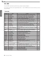
Page 80: ...he specified segment EVENT 15 Thin Out Reduce repetitions of specified event type within specified segment EVENT 16 Modify Control Data Changes of offsets the values of all occurences of the specified type of control change data with the specified segment EVENT 17 Time Stretch Expand or compress timing over specified segment PHRASE 18 Copy Phrase Copy phrase into specified destination PHRASE 19 Ex...

Page 81: ... the button for continu ous scrolling When the desired job has been highlighted press the Select function button F4 below Select on the display Numeric Selection Use the numeric entry method described on page 26 to enter the number of the desired job The job number will flash in the upper right corner of the display Then press the EXIT button Parameter Values Function Category UNDO REDO NOTE EVENT...

Page 82: ...The two entries at the bottom of the screen identify the data change currently available for undoing or redo ing This will be the most recently executed editing recording or job related data change In the example above the most recent change was made by running the Quantize job under the PATTERN mode Note Job 01 Quantize 1 3 2 4 5 6 This job quantizes note events over a specified segment of a spec...

Page 83: ...ze value Quantizing strength 100 where quantize value Settings 000 100 5 Swing rate This setting lets you apply a delay to the notes in every even numbered quantizing interval but see below to produce a more swinging rhythm This adjustment is car ried out after quantizing is completed first the notes are quantized and then the swing delay if any is applied If you are using a 32nd 16th 8th or quart...

Page 84: ...ll 6 Swing Gate Time This value applies a proportional adjustment to the gate timing of the notes within the swing adjusted intervals The gate time is the length of time that a note is held You can use this setting therefore to lengthen or shorten the notes in the swing adjusted intervals A setting of 100 leaves the original gate time un changed Higher settings increase the gate time while lower s...

Page 85: ...nge Positive values increase the velocity while negative values decrease it Settings 99 00 99 Original velocities Offset 20 Vel 96 64 32 127 96 Offset 20 Vel 116 84 52 127 116 Vel 76 44 12 107 76 Job 03 Modify Gate Time 1 3 2 4 5 This job alters the gate times of the specified range of notes pitches in the specified segment of the designated track The gate time refers to the length of time that a ...

Page 86: ... Offset This parameter adds a fixed value to each of the Rate adjusted gate times A setting of 0 produces no change Positive values increase the gate time while negative values decrease it Settings 9999 0000 9999 Original gate timing Offset 20 Offset 20 Gate Gate Gate 32 32 32 48 48 12 12 12 28 28 52 52 52 68 68 Job 04 Crescendo 1 3 2 You use this job to apply a crescendo or decrescendo to the spe...

Page 87: ... point the second segment sets the end point Settings Measure beat clock 001 1 000 257 1 000 3 Note range Note C 2 G8 Sets the note range to be transposed Settings C 2 G8 4 Transpose The Transpose value sets the number of transposition intervals semitones A value of 12 would transpose all targeted notes up by exactly one octave while a value of 12 would transpose down by an octave Settings 127 000...

Page 88: ...te events by order of pitch The sort is reflected in the EDIT page listing and determines the separation sequence used by the Chord Separate job see next page Sorting is by pitch If notes E3 C3 and G3 all begin at the same time the job adjusts the sequence to C3 E3 G3 if the Type setting is up to G3 E3 C3 if down 1 Phrase setting Phrs Sets the phrase to which adjustment is applied Settings 001 256...

Page 89: ... the selected track The shift is executed in clock cycle increments If you wish to move events by one or more full beats or meas ures you may find it easier to use the Copy Event job be low Note that this job will never move an event past the desig nated segment s start or end points any event that would oth erwise move past this point is instead deposited at the seg ment s border 1 Phrase setting...

Page 90: ...ingle control change message type 000 to 127 or all control change messages CAT Channel aftertouch PAT Polyphonic aftertouch EXC System exclusive ALL All events Job 13 Extract Event 1 3 2 4 This job moves all instances of specified event data from a selected segment of a phrase to the same segment on a differ ent phrase Following the operation the targeted events no longer exist in the source segm...

Page 91: ... the upper limit Settings 000 127 8192 8191 Event Type PB 7 Clock Specifies the number of clocks between each created event to be inserted Settings 001 999 8 Curve Specifies the degree of positive or negative curvature that will be applied to the continuous data 00 pro duces a linear curve Positive values create an increas ingly positive curve i e upward curve and negative values produce an increa...

Page 92: ...the amount of offset applied to the control change values settings reduce the values while settings increase the values New Control Change Values Original Control Change Values x rate 100 offset If the right side of the equation is less than 0 the new value becomes 1 Settings 127 127 8192 8191 Event Type PB Job 17 Time Stretch 1 2 3 This job expands or compresses the timing over the selected segme...

Page 93: ...ings U01 U50 2 Source phrase Phrase a The first Phrase value selects the source phrase This is the phrase containing the data to be mixed into the des tination phrase Following the mix the content of the source phrase remains unchanged Settings 001 256 3 Destination style Style b The second Style value selects the style containing the destination phrase phrase b Settings U01 U50 4 Destination phra...

Page 94: ...ation phrase The lower Phrase value selects the split destination Settings OFF 001 256 Job 23 Get Phrase 1 2 4 3 This job creates a user phrase from a specified segment of song data Specifically it copies a segment of sequence track data from a song into the designated destination phrase The RM1x sets the time signature meter for the new phrase equal to the meter recorded in the initial measure of...

Page 95: ...ected user phrase and reinitializes the phrase table 1 Phrase The Phrase value selects the user phrase to be deleted Settings 001 256 Job 26 Phrase Name You use this job to set or change the name for a non empty user phrase The name can be up to 8 characters long Use Display Knobs 1 and 2 to select a character location and character then press the F2 function button Enter to enter the specified ch...

Page 96: ...e the corresponding data type Do not exchange this data type Job 29 Clear Track 1 2 3 This job deletes all data of the selected type from the se lected pattern track or from all pattern tracks 1 Section The Sec setting selects the section to be cleared Settings A P 2 Track The TR setting selects the track to be cleared Settings 01 16 3 Data type These check boxes determine the type s of data to be...

Page 97: ...o a number or letter the RM1x automatically deselects the ALL setting at the desti nation side Settings Style U01 U50 Section A P ALL 2 Destination style section The second group of settings selects the destination style and section s Again if you set Section to ALL the RM1x auto matically sets the corresponding source value to ALL And if you change an ALL setting to a number or letter the RM1x au...

Page 98: ...ern 1 This job deletes all data from the selected pattern s If you set Style to ALL the job executes a total deletion removing all sections of all styles In this case the job also reinitializes all play effect and pattern voice settings for all styles Note that it is not possible to Undo a total deletion Be sure that you really want to delete all patterns before executing a Style ALL deletion If y...

Page 99: ...cation for example must identify the note the note name the note s time span the gate time and the note s force the velocity The first item on the event list is Top while the last item is End These items are for marking purposes only they do not represent events and they cannot be edited Measure Beat Clock Parameter Values Function Event type Note PB PC CC CAT PAT Specifies the type of event to be...

Page 100: ...System Exclusive System Exclusive XG Drum setup message using an XG parameter name Editing Existing Events To edit the data in the edit display use Display Knob 1 POINTER or the vertical cursor buttons to move the pointer to an event you want to edit use the lateral cursor buttons to move the cursor to the data item you want to edit then edit as required via either the NO 1 and YES 1 buttons or ke...

Page 101: ...elect MSB Bank Select LSB PC 000 127 000 127 000 127 4 Control Change 5 Channel aftertouch Ctrl Data 000 127 000 127 Data 000 127 Editable Event Parameters The parameters and value ranges for editable items are listed below For each type of event the main edit display is shown on the left while the corresponding insert edit display is shown on the right ...

Page 102: ...isplay Name MSB LSB PB Sens Pitch Bend Sensitivity 000 000 000 127 FnTune Fine tune 000 001 64 63 CsTune Coarse tune 000 002 64 63 Null Null 127 127 9 Exclusive Data Hex needs to be entered using hexadecimal values Refer to the MIDI Data Format section of the separate List Book for details MSB LSB Data 000 127 000 127 000 127 ...

Page 103: ...Resonance 021 Note C 2 G8 000 127 DrAtRt Drum EG Attack Rate 022 Note C 2 G8 000 127 DrDcRt Drum EG Decay Rate 023 Note C 2 G8 000 127 DrPtCs Drum Pitch Coarse 024 Note C 2 G8 000 127 DrPtFn Drum Pitch Fine 025 Note C 2 G8 000 127 DrLevl Drum Level 026 Note C 2 G8 000 127 DrPan Drum Pan 028 Note C 2 G8 000 127 DrRev Drum Reverb Send Level 029 Note C 2 G8 000 127 DrCho Drum Chorus Send Level 030 No...

Page 104: ... RevRtn Reverb Return 000 127 RevPan Reverb Pan L64 C R63 RevP11 Reverb Parameter 11 Refer to the Effect Parameter List section of the separate List Book for details RevP16 Reverb Parameter 16 ChoType Chorus Type ChoP1 Chorus Parameter 1 ChoP10 Chorus Parameter 10 ChoRtn Chorus Return 000 127 ChoPan Chorus Pan L64 C R63 ChToRv Send Chorus to Reverb 000 127 ChoP11 Chorus Parameter 11 Refer to the E...

Page 105: ...Part Mode PT01 PT99 NORM DRUM DrS1 DrS9 NtShft Note Shift PT01 PT99 64 63 Detune Detune PT01 PT99 12 8 12 7 Vol Volume PT01 PT99 000 127 VelDep Velocity Sens Depth PT01 PT99 000 127 VelOfs Velocity Sens Offset PT01 PT99 000 127 Pan Pan PT01 PT99 Rnd Random L63 C R63 NLim L Note Limit Low PT01 PT99 C 2 G8 NLim H Note Limit High PT01 PT99 C 2 G8 DryLvl Dry Level PT01 PT99 000 127 ChoSnd Chorus Send ...

Page 106: ...Pitch EG Initial Level PT01 PT99 64 0 63 PEGAtk Pitch EG Attack Time PT01 PT99 64 0 63 PEGRLv Pitch EG Release Level PT01 PT99 64 0 63 PEGRtm Pitch EG Release Time PT01 PT99 64 0 63 VelLmL Velocity Limit Low PT01 PT99 000 127 VelLmH Velocity Limit High PT01 PT99 000 127 15 XG system exclusive drum Parameter Set Note Data Display Name DrPcCs Drum Pitch Coarse Dr1 Dr9 C 2 G8 64 0 63 DrPcFn Drum Pitc...

Page 107: ...editing screens to remind you that the filter is on As an example assume that you want to work on note events only In this case you will probably want to filter out all other event types from the event list since this will make the list easier to follow and will protect against accidental changes to other events To set the filter to block out all non note events remove checkmarks from all boxes ot...

Page 108: ...spose 36 36 Shows the current transpose value Transposition can be accom plished via this parameter or by the keyboard method described on page 27 Measure 001 256 Sets playback start location or shows current playback location After specifying the start and end measures of the range of pattern data you want to copy from the current style and sec tion and after specifying the destination style and ...

Page 109: ...REMIXER 109 PATTERN CHAIN MODE Chapter 3 PATTERN CHAIN MODE The PATTERN CHAIN mode makes it possible to specify a sequence of patterns to be played back automatically 1 PATTERN CHAIN Playback 110 2 Disk 111 3 Job 112 ...

Page 110: ...tern will begin playing from measure 005 2 Enter a pattern at the selected measure Use Display Knob 2 to specify a style and display knob 4 to specify the section of the style correspond ing to the desired pattern OFF and END meas ures can be entered via Display Knob 2 You can also specify the section via the keyboard as described on page 28 It is not necessary to re enter the style and section fo...

Page 111: ...Disk functions in the PATTERN CHAIN mode are essentially the same as those in the PATTERN mode except that only the ALL file type is available Refer to the PATTERN mode disk functions beginning on page 76 Save Load Rename Delete Format Information 2 Disk ...

Page 112: ... Measure Insert empty measures into all tracks MEASURE 04 Delete Measure Delete specified measures from all tracks CONVERT 05 Convert to Song Converts the Pattern Chain data to Song data and places the results in the normal song tracks after converting the data to standard MIDI format CHAIN 06 Copy Chain Copy data from selected pattern chain into destination pattern chain CHAIN 07 Clear Chain Dele...

Page 113: ...nserts one or more empty measures into the same location on all tracks 1 Insertion point The M value sets the position for the insertion Spe cifically the value sets the measure number within the pattern chain for the first inserted measure A value of 001 for example inserts the measures at the very be ginning so that the first inserted measure becomes Measure 1 Settings 001 999 2 Time signature Y...

Page 114: ...elected pattern chain will exist at two pattern chain locations The copy operation causes loss of any data already existing in the destination pattern chain 1 Source pattern chain The first Chain value selects the Pattern chain to be copied Settings 01 20 2 Destination pattern chain The second Chain value selects the destination Settings 01 20 3 Job Job 07 Clear Chain 1 This job deletes all data f...

Page 115: ...gs Each song can comprise as many as 16 sequence tracks and 1 BPM tempo track Playback and recording in the SONG mode is essentially the same as in the PATTERN mode Conceptually the only differ ence is that the SONG mode is designed for recording and playing back complete songs while the PATTERN mode is in tended for recording and playing shorter phrases and patterns The only functional difference...

Page 116: ...tion or shows current playback location Time Signature 1 16 16 16 1 8 Sets the song s time signature 16 8 1 4 8 4 Track status M S Indicates track SOLO or track MUTE The highlighted track number indicates the currently selected track To select and play a song 1 Make sure the SONG mode is selected if neces sary press the MODE SONG button SONG should appear in the upper left hand corner of the LCD d...

Page 117: ...DI channels Please note that only the REPLACE OVERDUB and PUNCH IN recording modes are available when MULTI is selected Recording type Replace Realtime Selects the recording method Overdub Realtime Punch In Realtime Step Step Grid Step Keypad velocity 001 127 RND1 RND4 Specifies the note velocity value for the RM1x keyboard Higher val ues produce louder sound BPM 25 300 Sets tempo for song playbac...

Page 118: ...nd punch out meas ure and beat parameters and set as required Then before actually starting recording set the measure parameter a few measures before the punch in point so you ll be ready to record when the punch in point is reached 4 Start the punch in operation by pressing the PLAY p button there is no count in when punch in re cording is started Recording will begin automatically at the specifi...

Page 119: ...de Harmonize Play Fx 5 MIDI delay Same as in the PATTERN mode Refer to page 60 The only difference is that in the SONG mode you will not need to specify a section since the concept of sections only applies in the PATTERN mode Delay Feedback 6 Arpeggio Same as in the PATTERN mode Refer to page 62 The only difference is that in the SONG mode you will not need to specify a section since the concept o...

Page 120: ...N mode Voice Balance Effect Send 8 Voice Edit Same as in the PATTERN mode Refer to page 65 The only difference is that in the SONG mode you will not need to specify a section since the concept of sections only applies in the PATTERN mode EG Pitch Bend Portamento LFO Filter 9 Effect Same as in the PATTERN mode Refer to page 69 Type When variation connection System When variation connection Insertio...

Page 121: ...ection System When variation connection Insertion page2 When variation connection System When variation connection Insertion Chorus edit page1 page2 Reverb edit page1 page2 10 Setup Same as in the PATTERN mode Refer to page 73 Low Boost Knob Assign Out Channel 9 Effect 10 Setup ...

Page 122: ...ially the same as those in the PATTERN mode except that the PATT file type is not available Refer to the PATTERN mode disk functions beginning on page 76 Also refer to the About Floppy Disks section on page 42 for additional information Save Load Rename Delete Format Information 11 Disk ...

Page 123: ...on EVENT 12 Erase Event Erase all events over selected segment and replaces with rests EVENT 13 Extract Event Move events of specified type from specified segment of one phrase to same segment in another EVENT 14 Create Continuous Data Creates the specified type of continuous control change data in the specified segment EVENT 15 Thin Out Reduce repetitions of specified event type within specified ...

Page 124: ...er than a PHRASE and the selectable measure range is greater Refer to page 82 Job 02 Modify Velocity Essentially the same as in the PATTERN mode except that a TRACK is selected rather than a PHRASE and the selectable measure range is greater Refer to page 84 Job 03 Modify Gate Time Essentially the same as in the PATTERN mode except that a TRACK is selected rather than a PHRASE and the selectable m...

Page 125: ... that a TRACK is selected rather than a PHRASE and the selectable measure range is greater Refer to page 88 Job 08 Chord Sort Essentially the same as in the PATTERN mode except that a TRACK is selected rather than a PHRASE and the selectable measure range is greater Refer to page 88 Job 09 Chord Separate Essentially the same as in the PATTERN mode except that a TRACK is selected rather than a PHRA...

Page 126: ...t a TRACK is selected rather than a PHRASE and the selectable measure range is greater Refer to page 92 Job 17 Time Stretch Essentially the same as in the PATTERN mode except that a TRACK is selected rather than a PHRASE and the selectable measure range is greater Refer to page 92 Measure Job 18 Create Measure 1 3 2 This job inserts one or more empty measures into the same location on all tracks 1...

Page 127: ...fer to page 96 Job 22 Mix Track 1 4 2 a b b This job mixes all data from a selected sequence track onto another sequence track The two tracks do not have to be in the same song When the operation is completed the source track remains unchanged while the destination track contains both its origi nal data and a copy of the source track s data 1 Source track Track a The first TR value selects the sou...

Page 128: ...nce the concept of sections only applies in the PATTERN mode Settings Song U01 U20 Job 27 Clear Song Same as in the PATTERN mode Refer to page 98 The only difference is that in the SONG mode you will not need to specify a section since the concept of sections only applies in the PATTERN mode Settings Song U01 U20 Job 28 Song Name Same as in the PATTERN mode Refer to page 98 12 Job 13 Edit 13 Edit ...

Page 129: ...number U01 U60 Specifies the destination style number Section A P Specifies the destination section DO Press the F4 function button DO to actually cut and copy the speci fied song data to the specified style and section Track number 01 16 Shows the current selected track number Track number selection can be accomplished via this parameter or by the keyboard method described on page 27 Transpose 36...

Page 130: ...SONG MODE 130 RM1x SEQUENCE REMIXER MEMO ...

Page 131: ...NCE REMIXER 131 UTILITY MODE Chapter 5 UTILITY MODE This chapter explains Utility mode Utility mode is where you can make system settings and MIDI related settings 1 System 132 2 MIDI Setup 135 3 MIDI filter 137 ...

Page 132: ... desired tempo Parameter Values Function Master tune 102 4 0 102 3 Sets the overall tuning of the entire RM1x in 0 1 cent steps The pitch of drum voices cannot be adjusted here One cent is 1 100th of a semitone Footswitch START STP SEC SUS TAP Sets the function of the footswitch connected to the rear panel FOOT SW connector For details see the list below Pattern Quantize 1 1 16 Sets the quantize v...

Page 133: ...F 1 Meas 2 Meas 3 Meas 4 Meas 5 Meas 6 Meas 7 Meas 8 Meas Parameter Values Function Event chase OFF See below PC PC PB CTRL ALL System exclusive interval time See below Edit view NORM RM1x TG Specifies the normal NORMAL or RM1x TG edit view mode for the PATTERN and SONG EDIT modes When the RM1x TG mode is selected the EDIT mode display will conform to the parameters of the RM1x tone generation blo...

Page 134: ... is set toALL large amounts of MIDI data will be transmitted from the MIDI OUT connector which can cause MIDI errors to occur on the external MIDI device that is re ceiving this data Settings OFF Event Chase will not be performed PC Program Change events PC PB CTRL Program Change Pitch Bend and Control Change events ALL All events other than notes 1 System System exclusive interval time When syste...

Page 135: ...ta is both transmitted and received Echo back OFF THRU RecM Echo Back is a function by which data received at a MIDI IN con nector is re transmitted from a MIDI OUT connector These param eters are the echo back settings hours minutes seconds frames Hours 00 23 Minutes 00 59 Seconds 00 59 Frames 00 29 Internal With a setting of Internal the RM1x will use its own internal clock Select this setting i...

Page 136: ... param out OFF ON When parameter values are modified in Voice submode or Effect submode this setting specifies whether the operation will be trans mitted in realtime from the MIDI OUT connector as MIDI data When set to OFF MIDI will not be output Voice setup to TG OFF ON Determines whether the corresponding voice and effect settings will be sent to the RM1x tone generator when a song or style is s...

Page 137: ...h as Modulation Wheel Pan and Volume Channel Specify whether or not MIDI Channel Aftertouch messages will be passed Aftertouch Polyphonic Specify whether or not MIDI Polyphonic Aftertouch messages will be passed Aftertouch System Specify whether or not MIDI System Exclusive messages will be passed Exclusive MIDI System Exclusive messages are used to reset the tone generator and to operate internal...

Page 138: ...138 RM1x SEQUENCE REMIXER UTILITY MODE MEMO ...

Page 139: ...RM1x SEQUENCE REMIXER 139 APPENDIX APPENDIX 1 Specifications 140 2 Troubleshooting 142 3 Error Message 144 4 Glossary 146 5 Index 150 ...

Page 140: ...Note offset Clock shift Gate time offset Velocity offset Play Fx Harmonize Unison Octaver Harmonize1 2 Play Fx Beat stretch Clock shift Gate time Velocity offset MIDI delay MIDI delay edit Feedback edit Arpeggio Type Up Down Alternate1 2 Random Sort Hold Octave range Sequence file formats RM1x native sequence format SMF format 0 Demo song 4 Included disk Tone generator block Type AWM2 tone generat...

Page 141: ...ht adjustable contrast LED indicators MODE x 4 green REC red PLAY green TRACK x 16 red KEYBOARD MODE MUTE red SECTION red ARPEGGIO ON red FUNCTION BUTTON red x 4 KNOB A B red MIDI IN red MIDI OUT green 7 segments LED x 4 Connectors PHONES stereo phone jack OUTPUT phone jack x 2 L MONO R FOOT SW DC IN MIDI IN MIDI OUT Floppy disk drive 3 5 inch 2HD MF2HD and 2DD MF2DD types Power supply AC adaptor ...

Page 142: ...73 Are you using a PLAY FX Harmonize UNISON setting This can sometimes sound like distortion Page 57 Pitch is different than the keyboard note that was played Is the Master Tune parameter set to an extreme value Page 132 Is the Note Shift setting other than 0 Page 47 Is the Transpose setting other than 0 Page 46 Is the Groove function set to offset any notes Page 55 Make sure that the pitch bend k...

Page 143: ...s and phrases This means that if there are songs or phrases which contain large amounts of data the memory may be full even though there are still unused songs or patterns Can t record a phrase or song Have you selected a preset pattern or phrase You can only record to user patterns or phrases Page 46 Is the Memory Protect turned on Page 132 Can t receive or transmit MIDI bulk data Is the System e...

Page 144: ...in a pattern having more than the maximum of 256 measures Phrase Number Overflow All available user phrases 256 maximum have been used up when recording executing a job or editing System Backup Battery Low This will appear when the internal backup battery of the RM1x has run down Contact nearest Yamaha dealer or the authorized distributer for your country to have the battery replaced Memory Full T...

Page 145: ...e exchanged disks when you should not have Try the operation once again from the beginning Can t Change File Name When renaming this will appear if the floppy disk already contains a file with a name identical to the specified filename Specify a different filename Illegal File When loading this will appear if the specified file cannot be handled by the RM1x Check the contents of the file No Data W...

Page 146: ...n of the signal above that frequency This frequency is referred to as the cutoff frequency D Decay time The time from when the maximum volume of a note is reached until it falls to the sustain level Delay An effect or device that delays an audio signal The RM1x s Variation effect allows a delay to be applied Depth The amount or degree of a setting or effect Dry sound The audio signal that is not p...

Page 147: ...ents today implement the MIDI specification and provide MIDI connectors Such in struments can be connected together to create remote per formance or automatic performance systems MIDI data filer A MIDI device that receives data for the internal settings of a MIDI device in the form of System Exclusive messages and stores them to floppy disk An example is the Yamaha MDF3 MIDI data filer Modulation ...

Page 148: ...ated by recording performance data on one or more tracks Standard MIDI File SMF SMF is an acronym for Standard MIDI File a format that allows easy exchange of song data be tween different sequencers Most of today s software and hardware manufacturers provide software hardware that can read and write Standard MIDI Files Step recording The method of recording in which music is input by entering note...

Page 149: ... degree of the effect is adjusted by mixing the sound that passes through the effect the wet sound with the sound that bypasses the effect the dry sound X XG A tone generator format developed byYamaha which expands the GM specification to provide the richer expressiveness and upward data compatibility that is demanded by today s more sophisticated computer peripheral environment 4 Glossary ...

Page 150: ...reate Roll 88 125 Crescendo 86 125 Cursor Buttons 12 Cutoff 68 D Data backup 43 DC IN Jack 14 Decay 65 Delay 60 119 Delay level 60 Delay time 60 Delete Measure 113 127 Delete Format Information 79 111 122 Disk 76 111 122 Disk in use indicator 15 DISPLAY Buttons 12 Display Knobs 12 26 Divide Drum Track 97 128 Dry level 64 E Echo back settings 136 Edit 99 128 Edit view 133 Editable Event Parameters ...

Page 151: ...rmalize Play Effect 96 127 Note 82 101 124 Note Display 53 Note shift 47 NRPN 102 NUM 27 Numeric Entry 26 Numeric POINTER Display 53 O Octaver 57 OCT DOWN and OCT UP Buttons 13 Out Channel 75 121 Overdub 51 118 P PAD Entry 53 PAD VELO 46 Pan 63 Patch 47 Pattern 35 97 PATTERN CHAIN MODE 32 PATTERN CHAIN Playback 110 PATTERN MODE 32 PATTERN Playback 46 Pattern Quantize 132 PB Events 53 PHONES Jack 1...

Page 152: ...Style Name 98 Submodes 23 System 132 System Effects 39 System exclusive interval time 134 System Initialization 30 T TAP ENTER Button 13 TG Header 43 Thin Out 91 126 Time stretch 92 126 Tone generator block 34 37 Track 27 95 127 Transpose 27 87 125 Type 69 120 U Unde Redo 29 82 113 124 Unison 57 Used Memory display 29 UTILYTY MODE 33 131 V Variation edit 70 121 Variation effect 39 Velocity offset ...

Page 153: ... Gata 1 Box 30053 S 400 43 Göteborg Sweden Tel 031 89 34 00 DENMARK YS Copenhagen Liaison Office Generatorvej 8B DK 2730 Herlev Denmark Tel 44 92 49 00 FINLAND Warner Music Finland OY Fazer Music Aleksanterinkatu 11 P O Box 260 SF 00101 Helsinki Finland Tel 0435 011 NORWAY Norsk filial av Yamaha Scandinavia AB Grini Næringspark 1 N 1345 Østerås Norway Tel 67 16 77 70 ICELAND Skifan HF Skeifan 17 P...

Page 154: ...M D G EMI Division Yamaha Corporation 1998 V343990 810CMIT18 2 02B0 Printed in Japan ...

Reviews: