background image

PSR-E303/YPT-300

23

 YAMAHA                     [ PORTATONE ]                    Date:15-Nov-2004
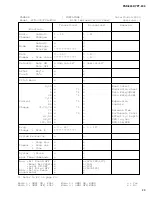
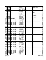
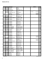
 Model  YPT-300/PSR-E303         MIDI Implementation Chart        Version:1.0

Transmitted

Recognized

Remarks

Function...

Basic

Default

1 - 16   

1 - 16

Channel

Changed

x

x

Default

3

3

Mode

Messages

x

x

Altered

**************

x

Note

0 - 127

0 - 127

Number  : True voice

**************

0 - 127

Velocity

Note ON

o 9nH,v=1-127

o 9nH,v=1-127

Note OFF

x

x

After

Key's

x

x

Touch

Ch's

x

x

Pitch Bend

x

o

0,32

o

o

Bank Select

1

x

*1

o

Modulation wheel

6

x

*1

o

Data Entry(MSB)

38

x

*1

x

Data Entry(LSB)

7,10

o

o

Control

11

x

*1

o

Expression

64

o

o

Sustain

Change

71,73,74

x

*1

o

Prog

o 0 - 127

o 0 - 127

Change  : True #

**************

System Exclusive

o

o

        : Song Pos.

x

x

Common  : Song Sel.

x

x

        : Tune

x

x

System   : Clock

o

o

Real Time: Commands

o

o

Aux  :All Sound OFF

x

o(120,126,127)

     :Reset All Cntrls x

o(121)

     :Local ON/OFF

x

o(122)

     :All Notes OFF

x

o(123-125)

Mes- :Active Sense

o

o

sages:Reset

x

x

72

o


o

Release Time

84

x

*1

o

Portamento Cntrl

91,93

o

o

Effect 1,3 Depth

96,97

x

o

RPN Inc,Dec

100,101

x

o

RPN LSB,MSB

*1 Refer to #2 on page 24.

Mode 1 : OMNI ON , POLY     Mode 2 : OMNI ON ,MONO

o : Yes

Mode 3 : OMNI OFF, POLY     Mode 4 : OMNI OFF,MONO

x : No 

Summary of Contents for PORTATONE PSR-E303

Page 1: ...OUT 4 CIRCUIT BOARD LAYOUT WIRING 5 BLOCK DIAGRAM 6 DISASSEMBLY PROCEDURE 7 LSI PIN DESCRIPTION 11 IC BLOCK DIAGRAM 13 CIRCUIT BOARDS 14 TEST PROGRAM 18 BACKUP INITIALIZATION 20 TRANSFERRING DATA BETWEEN THE PSR E303 YPT 300 and a COMPUTER 21 MIDI IMPLEMENTATION CHART 23 MIDI DATA FORMAT 24 PARTS LIST OVERALL CIRCUIT DIAGRAM PK 001734 PSR E303 YPT 300 ...

Page 2: ...med by an authorized Yamaha Retailer or the appointed service representative IMPORTANT This presentation or sale of this manual to any individual or firm does not constitute authorization certifi cation recognition of any applicable technical capabilities or establish a principal agent relationship of any form The data provided is belived to be accurate and applicable to the unit s indicated on th...

Page 3: ... Send Level Dual voice Voice Volume Octave Chorus Send Level Split voice Voice Volume Octave Chorus Send Level Reverb Type Reverb level Chorus Type Panel Sustain Harmony Type Harmony Volume PC mode PC1 PC2 Off Local On Off External Clock Initial Setup Send Time Signature Metronome Volume Lesson Track R Lesson Track L Demo Cancel Effects Reverb 9 types Chorus 4 types Harmony 26 types Song 102 Prese...

Page 4: ...u FUNCTION button i SONG button o STYLE button 0 VOICE button 1 Number buttons 0 9 YES NO 2 DEMO button 3 METRONOME ON OFF button When the Song mode 4 A B REPEAT button 5 REW button 6 FF button 9 PAUSE button When the Style mode 4 ACMP ON OFF button 5 INTRO ENDING rit button 6 MAIN AUTO FILL button 9 SYNC START button 7 TEMPO TAP button 8 REC button 0 START STOP button 1 PORTABLE GRAND button 2 SO...

Page 5: ...61H CN3 DMLCD CN831 DMLCD CN832 DMLCD CN833 PNAM1 3 CN101 PNAM1 3 CN102 DMLCD CN131 PNAM3 3 CN402 Speaker L Speaker R DMLCD CN531 PNAM2 3 CN502 DMLCD CN631 61L CN4 12P 5P 3P 3P 2P 11P L 170 5P L 120 2P L 280 2P L 220 16P L 100 10P L 340 9P L 70 12P L 210 WE138500 WE138700 WE138800 WE15140 WE14140 WE13910 WE13900 WE14120 WE14130 WE14080 WE13970 WE14060 V8696200 The parts with in Part No are not ava...

Page 6: ...PEAKER R SPEAKER L MASTER VOLUME PHONES OUTPUT DC IN 12V 2 5V 2 5V 3 3D 3 3D 3 3D 3 3D 5D 3 3D 5D 5D 5A1 5A1 5A2 5A2 L R L R B IC101 3P IC132 3P IC431 16P IC432 8P IC701 80P IC131 3P TR101 102 4Ω 12cm 4Ω 12cm RXD0 TXD0 SCLK PF0 IRQ0 Power SS PF0 Power Select IRQ0 Power SS PF0 Power Select SDO SYSCK BCLK WCLK PB0 PB7 PA0 PA7 PA0 PA7 RS ENB MD00 15 MA01 22 UWR CAS LWR LUAS LCAS MD00 15 MA01 09 MD00 ...

Page 7: ...ZN2Y VI064600 When installing the DMLCD circuit board tighten the screws 1 through 8 in numerical order Fig 2 If the DMLCD circuit board is replaced execute the Factory Set in the test program 3 LCD Time required About 3 minutes 3 1 Remove the lower case assembly See procedure 1 3 2 Remove the DMLCD circuit board See procedure 2 3 3 Remove the LCD holder and rubber connector 3 4 Remove the back li...

Page 8: ... required About 3 minutes 4 3 1 Remove the PNAM circuit board 3 3 4 3 2 Remove the twelve 12 screws marked 150B The PNAM circuit board 1 3 can then be removed Fig 2 4 4 PNAM circuit board 2 3 Time required About 3 minutes 4 4 1 Remove the nine 9 screws marked 150C The PNAM circuit board 2 3 can then be removed Fig 2 5 Speaker Time required About 3 minutes 5 1 Remove the lower case assembly See pro...

Page 9: ...bly See procedure 7 9 2 Remove the keyboard corresponding to the rubber contacts to be removed See procedure 8 9 3 Remove the rubber contacts Photo 2 10 Circuit Board 61L Circuit Board 61H 10 1 Remove the lower case keyboard assembly See procedure 7 10 2 Circuit Board 61L Time required About 6 minutes 10 2 1 Remove the keyboards from C1 to B3 See procedure 8 10 2 2 Remove the four 4 screws marked ...

Page 10: ... it out from inside Fig 7 180 Bind Head Tapping Screw B 3 0X8 MFZN2Y EP600250 190 Bind Head Tapping Screw P SP 3 0X12 MFZNBL VZ313100 Fig 6 1 B Spring Terminal C Spring Terminal D 11 1 Remove the battery lid assembly at the bottom side of the lower case keyboard assembly 11 2 Remove the hooks to pull out the spring terminal C and spring terminal D Fig 7 8 Fig 7 Photo 3 Soldering Spring Terminal A ...

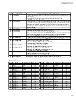
Page 11: ... 57 PB0 I O 58 PB1 I O 59 PB2 I O 60 PB3 I O Parallel port B 61 PB4 I O 62 PB5 I O 63 PB6 I O 64 PB7 SYI I O Parallel port B 65 VSS Ground 66 IOVDD Power supply 67 LBN LWRN PF6 O Low byte enable 68 UBN UWRN PF7 O Upper byte enable 69 RDN PF4 O Read enable 70 MD00 I O 71 MD08 I O 72 MD01 I O 73 MD09 I O Memory data bus 74 MD02 I O 75 MD10 I O 76 MD03 I O 77 VSS Ground 78 MD11 I O 79 MD04 I O 80 MD1...

Page 12: ... signal for LCD driver outout Display data interface Read write Enable Data interface Data interface FUNCTION PIN NO 41 42 43 44 45 46 47 48 49 50 51 52 53 54 55 56 57 58 59 60 61 62 63 64 65 66 67 68 69 70 71 72 73 74 75 76 77 78 79 80 I O I O I O I O I O I O I O O O O O O O O O O O O O O O O O O O O O O O O O O O O O O O O O O O DB2 DB3 DB4 DB5 DB6 DB7 C1 C2 C3 C4 C5 C6 C7 C8 C9 C10 C11 C12 C13 ...

Page 13: ...FR AOUTL AOUTL AOUTR AOUTR VDD VSS DZFL DZFR AOUTL AOUTL AOUTR AOUTR Σ Modulator Σ Modulator µP Interface De emphasis Control Clock Divider Audio Data Interface 8X Interpolator 8X Interpolator SCF SCF CSN NJM4580E X2331A00 Dual Operational Amplifier DMLCD IC432 1 2 3 4 V 8 7 6 5 A Output V A INPUT V V B Output B INPUT B INPUT A INPUT SN74LV138ANSR ISO013810 DECODER DMLCD IC831 832 1 2 3 4 5 6 7 A ...

Page 14: ...R TEMPO TAP LESSON PART R LESSON PART L STANDBY ON FF REW A B REPEAT PNAM1 3 Circuit Board 2NA WE00540 1 CIRCUIT BOARDS DMLCD Circuit Board X5910C0 16 PNAM 1 3 Circuit Board X5911C0 14 PNAM 2 3 Circuit Board X5911C0 15 PNAM 3 3 Circuit Board X5911C0 15 61H Circuit Board X2335C0 17 61L Circuit Board X2336B0 17 Note See parts list for details of circuit board component parts Component side ...

Page 15: ...FECT KIT PEVERB ON OFF SPLIT ON OFF DUAL ON OFF HARMONY ON OFF TOUCH ON OFF METRONOME ON OFF DEMO 7 4 1 0 8 5 2 9 6 3 SUSTAIN MIDI OUT IN to DMLCD CN631 to DMLCD CN531 PNAM2 3 Circuit Board to PNAM1 3 CN401 MASTER VOLUME PNAM3 3 Circuit Board PNAM2 3 2NA WE00540 1 PNAM3 3 2NA WE00540 1 Component side Component side ...

Page 16: ...PSR E303 YPT 300 16 to PNAM2 3 CN601 to PNAM2 3 CN501 to 61H CN2 to 61H CN1 to 61L CN5 to PNAM1 3 CN103 not installed DMLCD Circuit Board Component side Pattern side 2NA WE00520 1 ...

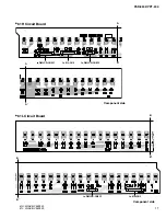
Page 17: ...SR E303 YPT 300 17 B B to DMLCD CN833 to 61H CN3 B B to DMLCD CN831 to 61L CN4 to DMLCD CN832 A A A A Component side Component side 61H 2NAKB V869540 61L 2NAKB V869520 61H Circuit Board 61L Circuit Board ...

Page 18: ...ONES R 1 5dBu 2dB 8 015 Output L Connect the level meter with JIS C filter to the L R terminals of the PHONES OUTPUT 33Ω of load Set the MASTER VOLUME to the maximum level and check the output level PHONES L 1 5dBu 2dB PHONES R 45 0dBu or less 1 Preparation 1 Use an AC adaptor PA 3C or PA 32 2 Measuring device Frequency counter which can detect thousandth digit Level meter with JIS C filter Note C...

Page 19: ...check 16 042 Ram Chk2 Checks the RAM connected to the CPU bus Make sure that Ram OK is displayed on the LCD 17 045 FRomChk2 Checks the FROM connected to the CPU bus Make sure that FRom OK is displayed on the LCD It will take about 30 seconds for the check 18 047 Factory Set Initializes the entire backup area to reset to the factory default Fact is displayed on the LCD during the test Fact End is d...

Page 20: ...ly hold down the highest white key and the three highest black keys on the keyboard and turn the power on by pressing the STANDBY ON switch When you execute the Flash Clear operation Song data you have pur chased and downloaded will also be cleared Make sure to save your impor tant data by transferring to a computer using Musicsoft Downloader STANDBY ON BACKUP INITIALIZATION Backup Some internal p...

Page 21: ...oft Downloader http music yamaha com download OS Windows 98SE Me 2000 XP Home Edition XP Professional CPU 233 MHz or higher Intel Pentium Celeron processor family 500 MHz or more is recommended Memory 64 MB or more 256 MB or more is recommended Hard Disk at least 128 MB of free space at least 512 MB of free space is recommended Display 800 x 600 HighColor 16 bit Other Microsoft Internet Explorer 5...

Page 22: ...ollowing cases During Style playback During Song playback NOTE Close the window to exit from the Musicsoft Downloader and re enable control of the instrument You can transfer backup data including the five User Songs stored to the instrument to a computer as a user file by using Musicsoft Downloader For details about how to transmit Song data using the Musicsoft Downloader application refer to the...

Page 23: ...x 1 o Data Entry MSB 38 x 1 x Data Entry LSB 7 10 o o Control 11 x 1 o Expression 64 o o Sustain Change 71 73 74 x 1 o Prog o 0 127 o 0 127 Change True System Exclusive o o Song Pos x x Common Song Sel x x Tune x x System Clock o o Real Time Commands o o Aux All Sound OFF x o 120 126 127 Reset All Cntrls x o 121 Local ON OFF x o 122 All Notes OFF x o 123 125 Mes Active Sense o o sages Reset x x 72...

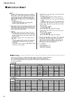
Page 24: ... is ignored By default factory settings the instrument ordinarily functions as a 16 channel multi timbral tone generator and incoming data does not affect the panel voices or panel settings However the MIDI messages listed below do affect the panel voices auto accompaniment and songs When the accompaniment is started an FAH message is transmitted When accompaniment is stopped an FCH message is tra...

Page 25: ...second letter of the shaded part number is O not zero The second letter of the shaded part number is I not one M South African model O Chinese model Q South east Asia model T Taiwan model U U S A model V General export model 110V W General export model 220V N X General export model Y Export model A Australian model B British model C Canadian model D German model E European model F French model H N...

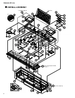
Page 26: ... 110 100 40 120 130 130 80 70 90 60 330 30 300 300 310 310 150 150 150 260 270 270 280 280a 280b 280c 240 240 240 250 L30 L20 L30 L20 L30 L20 L40 L10 L50 30 20 190 210 220 240 200 140 3 3 140 1 3 140 2 3 Lower case assembly Lower case keyboard assembly See page 4 Upper case assembly 320 320 ...

Page 27: ...ubber Connector 105X10 7 0 35WZ 2 03 200 Rubber Connector 2 210 LCD Holder 01 220 Circuit Board DMLCD 230 Connector Assembly BL 2P L 70 WE14140 240 Bind Head Tapping Screw B 3 0X12 MFZN2Y 15 01 250 Lower Case Keyboard Assembly WD89530 260 Lower Case Assembly 270 Bind Head Tapping Screw B 3 0X30 MFZN2Y 3 01 280 Battery Lid Assembly 280a Battery Cover WD87980 280b Battery Cushion WHITE WD87990 280c ...

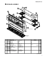
Page 28: ... 300 WD89530 10 Lower Case 20 Keyboard Assembly 16N C61 P2M WE12670 30 Connector Assembly MK1 12P L 220 40 Connector Assembly MK2 5P L 250 50 Connector Assembly MK3 7P L 190 60 Foot T1 6 3 01 70 Spring Terminal A 80 Spring Terminal B 90 Spring Terminal C 3 100 Spring Terminal D 2 110 Nonwoven Fabric Cloth WD89680 2 120 Connector Assembly BATT WE15140 10 20 60 120 30 40 50 Keyboard assembly See pag...

Page 29: ...M C61 P2 04 150b Circuit Board 61H 16N2M C61 P2 04 150c Connector Assembly 16N 2M C61 L 210 01 150d Felt U 02 160 Felt L 02 170 Rubber Sheet 01 180 Bind Head Tapping Screw B 3 0X8 MFZN2Y 7 01 190 Bind Head Tapping Screw P SP 3 0X12 MFZNBL 13 01 200 Bind Head Tapping Screw P 3 0X20 MFZN2Y 21 01 WB125200 WB125300 V4760300 VZ271700 V3413600 V7477400 V8695300 V8695500 V8696200 VZ302900 VZ303000 VH1814...

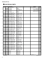
Page 30: ...RECT 01 0439 Ceramic Capacitor SL chip 680P 50V J RECT 01 C0440 Electrolytic Cap chip 4 7 50V UWX1H4 01 C0441 Electrolytic Cap chip 4 7 50V UWX1H4 01 C0442 Ceramic Capacitor SL chip 100P 50V J RECT 01 C0443 Ceramic Capacitor SL chip 100P 50V J RECT 01 C0444 Electrolytic Cap chip 100 10V 01 C0445 Ceramic Capacitor F chip 0 1000 25V Z RECT 01 C0446 Electrolytic Cap chip 10 16V 01 C0447 Ceramic Capac...

Page 31: ...9K 63M J RECT 01 R0447 Carbon Resistor chip 100 0 63M J RECT 01 R0448 Carbon Resistor chip 100 0 63M J RECT 01 R0449 Carbon Resistor chip 1 2K 63M J RECT 01 R0450 Carbon Resistor chip 1 5K 63M J RECT 01 R0451 Carbon Resistor chip 0 63M J RECT 01 R0531 Carbon Resistor chip 100 0 63M J RECT 01 0538 Carbon Resistor chip 100 0 63M J RECT 01 R0539 Carbon Resistor chip 1 0K 63M J RECT 01 0546 Carbon Res...

Page 32: ... Capacitor 0 1500 50V J RX TP C0416 Mylar Capacitor 0 1500 50V J RX TP 01 C0416 Mylar Capacitor 0 1500 50V J V551560 C0416 Mylar Capacitor 0 15 100V K FORM VS88690 C0416 Monolithic Mylar Capacitor ECQ V1H154JL3 01 C0417 Mylar Capacitor 0 1500 50V J RX TP C0417 Mylar Capacitor 0 1500 50V J RX TP 01 C0417 Mylar Capacitor 0 1500 50V J V551560 C0417 Mylar Capacitor 0 15 100V K FORM VS88690 C0417 Monol...

Page 33: ...FL20 03 L0601 Coil 20uH FL5R200QNT RX TP 01 L0601 Coil 20uH FL5R200QN FORMING R0101 Carbon Resistor 180 0 1 6J 26TP R0102 Carbon Resistor 180 0 1 6J 26TP R0104 Carbon Resistor 47 0K 1 6J 26TP R0105 Carbon Resistor 3 3K 1 6 J 26TP R0107 Carbon Resistor 10 0K 1 6J 26TP R0108 Carbon Resistor 22 0K 1 6J 26TP R0109 Carbon Resistor 12 0K 1 6J 26TP R0401 Carbon Resistor 10 0K 1 6J 26TP 0404 Carbon Resist...

Page 34: ...r Assembly PN1 16P L 100 WE14080 WA502 Connector Assembly PN2 10P L 340 WE13970 WA601 Connector Assembly JACK 9P L 70 WE14060 Circuit Board 61H 16N2M C61 P2 V869540 X2335C0 04 CN01 Wire Trap 52147 12P TE 01 CN02 Wire Trap 52147 5P TE 01 CN03 Wire Trap 52147 12P TE 01 D073 Diode 1N4148 DO 34 01 122 Diode 1N4148 DO 34 01 Circuit Board 61L 16N2M C61 P2 V869520 X2336B0 04 CN04 Wire Trap 52147 12P TE 0...

Page 35: ... AMP JACK PN BA33BC0FP X5889A00 REGULATOR 3 3V DMLCD IC131 1 INPUT 2 GND 3 OUTPUT 1 2 3 RH5RZ25CA X3679A00 REGULATOR 2 5V DMLCD IC132 1 3 2 1 GND 2 INPUT 3 OUTPUT DMLCD 28CC1 8834552 2 XX XX XX XX XX XX XX XX XX MIDI DAC AMP P B LCD CPU MEMORY REGULATOR 5V PNAM1 3 IC101 BA50BC0T X5887A00 1 2 3 3 OUTPUT 2 GND 1 INPUT PNAM 1 3 PNAM 3 3 POWER AMP REGULATOR 5V 28CC1 8834546 3 28CC1 8834546 3 Mylar Cap...

Reviews: