background image

15

Connections

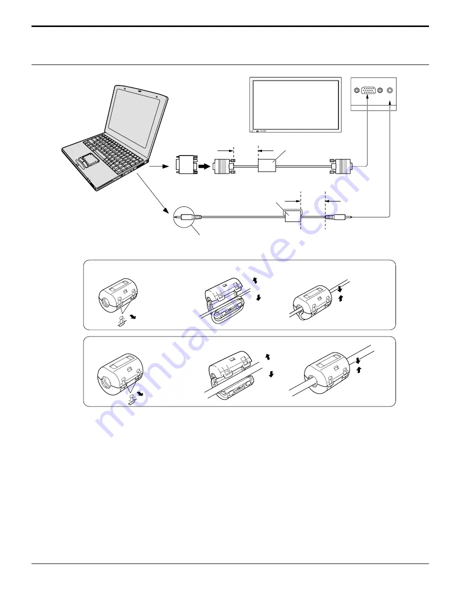
PC Input Terminals connection

Notes:
(1) Computer signals which can be input are those with a horizontal scanning frequency of 15.6 to 110 kHz and vertical

scanning frequency of 48 to 120 Hz. (However, the image will not be displayed properly if the signals exceed 1,200
lines.)

(2) The display resolution is a maximum of 1,024 

×

 768 dots when the aspect mode is set to “NORMAL”, and 1,366 

×

 768

dots when the aspect mode is set to “FULL”. If the display resolution exceeds these maximums, it may not be possible
to show fine detail with sufficient clarity.

(3) The PC input terminals are DDC1/2B-compatible. If the computer being connected is not DDC1/2B-compatible, you will

need to make setting changes to the computer at the time of connection.

(4) Some PC models cannot be connected to the set.
(5) There is no need to use an adapter for computers with DOS/V compatible D-sub 15P terminal.
(6) The computer shown in the illustration is for example purposes only.
(7) Additional equipment and cables shown are not supplied with this set.
(8) Do not set the horizontal and vertical scanning frequencies for PC signals which are above or below the specified

frequency range.

AUDIO

PC IN

COMPUTER

Conversion adapter 
(if necessary)

RGB

D-sub 15p

1/8" (3mm) stereo plug

PC cable

Connect a cable that matches
the audio output terminal on the computer.

POWER     /

R - STANDBY

G   POWER ON

INPUT

–   

VOL 

     +

Less than

3" 

15

/

16

(10 cm)

Audio

Less than

3" 

15

/

16

(10 cm)

Ferrite core (small size)

(supplied)

Ferrite core (large size)
(supplied)

Installing the ferrite core (Small size)

Pull back the tabs
(in two places)

Open

Press the cable
through and close

1

2

3

Installing the ferrite core (Large size)

Pull back the tabs
(in two places)

Open

Press the cable
through and close

1

2

3

Summary of Contents for PDM-1

Page 1: ...ITOR Operating Instructions English R STANDB Y G POWER ON INPUT VOL POWE R INPUT SURROUND VOL N R PICTURE SOUND SET UP ASPECT PICTURE POS SIZE OFF TIMER PC INPUT SURROUND VOL N R PICTURE SOUND SET UP ASPECT PICTURE POS SIZE OFF TIMER PC ...

Page 2: ...e appliance WARNING 1 To prevent electric shock do not remove cover No user serviceable parts inside Refer servicing to qualified service personnel 2 Do not remove the grounding pin on the power plug This apparatus is equipped with a three pin grounding type power plug This plug will only fit a grounding type power outlet This is a safety feature If you are unable to insert the plug into the outle...

Page 3: ...ns have been adhered to 9 Do not defeat the safety purpose of the polarized or grounding type plug A polarized plug has two blades with one wider than the other A grounding type plug has two blades and a third grounding prong The wide blade or the third prong are provided for your safety If the provided plug does not fit into your outlet consult an electrician for replacement of the obsolete outle...

Page 4: ...Supplied 8 Optional Accessories 8 Remote Control Batteries 9 Basic Controls 10 Connections 11 Basic connection 12 COMPONENT RGB Input connection 13 Speaker Terminals connection 14 PC Input Terminals connection 15 SERIAL Terminals connection 17 Power ON OFF and Input Signal Selection 18 AC cord connection 18 Power ON OFF 18 Select the Input Signal 19 Selecting the ON Screen Menu Language 19 On Scre...

Page 5: ...o comply with the requirements listed in FCC Regulations Part 15 for Class B digital devices Compliance with these require ments provides a reasonable level of assurance that your use of this product in a residential environment will not result in harmful interference with other electronic devices This equipment generates uses radio frequencies and if not installed and used according to the instru...

Page 6: ...eat may be generated which could cause fire If the plug is damaged or the wall socket plate is loose they should not be used Do not handle the power cord plug with wet hands Doing so may cause electric shocks Do not do anything that might damage the power cable When disconnecting the power cable hold the plug not the cable Do not make any modifications place heavy objects on place near hot objects...

Page 7: ...h Cleaning and maintenance The front of the display panel has been specially treated Wipe the panel surface gently using only a cleaning cloth or a soft lint free cloth If the surface is particularly dirty soak a soft lint free cloth in a weak detergent solution and then wring the cloth to remove excess liquid Use this cloth to wipe the surface of the display panel then wipe it evenly with a dry c...

Page 8: ...mall size 1 AC cord Fixing bands 2 Batteries for the Remote Control Transmitter AA R6 Battery 2 Ferrite core large size 2 Optional Accessories center speaker NS CF100 Pedestal PDS 150 Wall Mounting Unit PWK 150 For assembling Full instructions are supplied with each of the optional accessories for use with this plasma display Speaker Wire 2 Speakers main speaker NS F100 NS F80 for shelf placing NS...

Page 9: ...can cause battery leakage and corrosion that will damage the remote control transmitter Observe the following precautions 1 Batteries should always be replaced as a pair Always use new batteries when replacing the old set 2 Do not combine a used battery with a new one 3 Do not mix battery types example Zinc Carbon with Alkaline 4 Do not attempt to charge short circuit disassemble heat or burn used...

Page 10: ...e page 19 Sound mute On Off see page 26 VOLUME Adjustment Press the Volume Up or Down button to increase or decrease the sound volume level ACTION button Press to make selections ASPECT button Press to adjust the aspect see page 22 SOUND button see page 26 SET UP button see page 20 POSITION buttons R button see page 21 STAND BY ON OFF button The plasma display must first be plugged into the wall o...

Page 11: ... figure To secure cables connected to Terminals wrap the cable fixing band around them then pass the pointed end through the locking block as shown in the figure COMPONENT RGB IN andAudio IN Terminals see page 13 15 AV IN Terminals see page 12 15 From SERIAL Terminal on Computer see page 17 PR CR R PB CB B Y G COMPONENT RGB IN AV IN VD HD S VIDEO VIDEO R L AUDIO R L AUDIO AUDIO To tighten To loose...

Page 12: ... VIDEO AUX PROGRAM 6CH INPUT PRESET TUNING EDIT MEMORY MAN L AUTO FM TUNING MODE AUTO MAN L MONO TREBLE VIDEO AUX L AUDIO OPTICAL R PRESET TUNING BALANCE REC OUT ZONE 2 Center speaker NS CF100 Main speaker NS F100 Main speaker NS F100 Rear speaker Front effect speaker Rear speaker Front effect speaker Subwoofer Notes 1 Change the COMPONENT RGB IN setting in the SET UP menu to COMPONENT see page 34...

Page 13: ...nt being used 4 The quality of images obtained varies between connection methods in the descending order of Component Video S Video and Video Connections COMPONENT RGB Input connection COMPONENT RGB IN R L AUDIO Audio input to L R sockets G B R VD HD AUDIO 2 RCA audio cables 5 BNC RGB cables RGB input to R G B HD VD sockets BNC RCA adaptor plug Example of input signal source HDTV compatible VCR Co...

Page 14: ...onnect the speakers directly with the speaker terminals of the plasma display Refer to the speaker s Installation Manual for details on speaker installation Connections Make sure to use the supplied ferrite core speaker cables to connect the speakers Other types of speaker wires are not suitable Notes 1 Change the COMPONENT RGB IN setting in the SET UP menu to COMPONENT see page 34 2 Any equipment...

Page 15: ... cannot be connected to the set 5 There is no need to use an adapter for computers with DOS V compatible D sub 15P terminal 6 The computer shown in the illustration is for example purposes only 7 Additional equipment and cables shown are not supplied with this set 8 Do not set the horizontal and vertical scanning frequencies for PC signals which are above or below the specified frequency range AUD...

Page 16: ... vertical frequency kHz frequency Hz 1 525 480 60i 15 734 59 94 2 625 575 50i 15 625 50 3 525 480 60p 31 468 59 94 4 625 575 50p 31 25 50 5 750 720 60p 45 60 6 1 125 1 080 60i 33 75 60 7 1 125 1 080 50i 28 125 50 8 1 125 1 080 24p 27 24 9 1 125 1 080 24sF 27 48 PC input signal name horizontal vertical frequency kHz frequency Hz 1 640 400 70 31 5 70 2 640 400 60 31 5 59 94 3 Macintosh13 640 480 35 ...

Page 17: ...mand PON POF AVL AMT IIS DAM Control details Power ON Power OFF Volume 00 63 Audio MUTE OFF Audio MUTE ON Input select toggle VIDEO Mode COMPONENT RGB mode processed as a Y PB PR or RGB signals as set by this unit PC mode Screen mode select toggle NORMAL 4 3 ZOOM FULL JUST AUTO Parameter None None 0 1 None VID YP1 RG1 None NORM ZOOM FULL JUST SELF Command Basic format for control data The transmis...

Page 18: ...a display when the plasma display is on or in standby mode Remote Control Sensor Power Indicator Power ON OFF and Input Signal Selection When the POWER is turned on for the first time the LANGUAGE selection screen is displayed From the second time on language selection can be done from the setup menu see page 19 Select the desired language using the and keys and press the ACTION button From the se...

Page 19: ...UT see page 32 VIDEO COMPONENT PC VIDEO RGB PC R STANDBY G POWER ON INPUT VOL VOL INPUT INPUT SURROUND VOL N R INPUT Selecting the On Screen Menu Language press to display the SET UP menu press to select your preferred language selectable languages press to select the OSD LANGUAGE ENGLISH UK Deutsch Français Italiano Español ENGLISH US Chinese INPUT SURROUND VOL N R PICTURE SOUND SET UP SET UP SET...

Page 20: ... VIDEO S VIDEO and COMPONENT input signal modes NORMAL PICTURE POS SIZE NORMALIZE H POS H SIZE V POS V SIZE SET UP SIGNAL SCREENSAVER COMPONENT RGB IN SELECT RGB OSD LANGUAGE ENGLISH US SET UP TIMER SET UP SIGNAL SCREENSAVER COMPONENT RGB IN SELECT RGB OSD LANGUAGE ENGLISH US SET UP TIMER Press to select each item During RGB and PC input signal modes NORMAL PICTURE POS SIZE NORMALIZE H POS H SIZE ...

Page 21: ... Press the R button to return to SET UP menu Press to select each TIMER adjustment items When select TIMER adjustment item press this button to SET UP TIMER screen To SET UP TIMER selection screen see page 30 R FINISH TIME FINISH TIME 0 00 MINUTES ADJUSTMENT HOURS ADJUSTMENT 00 00 START TIME START TIME 0 00 00 MINUTES ADJUSTMENT 00 HOURS ADJUSTMENT PERIODIC TIME SHOW DURATION 0 00 MINUTES ADJUSTME...

Page 22: ...s pressed NORMAL ZOOM FULL AUTO JUST ASPECT Notes 1 During RGB and PC input signal modes the mode switches between NORMAL ZOOM and FULL only 2 For a 1 125i 1 080i 750p 720p signal input during COMPONENT input signal mode the mode is set to FULL mode and switching is not possible For a 525i 480i 625i 575i 525p 480p and 625p 575p signal input during COMPONENT input signal mode AUTO cannot be selecte...

Page 23: ...minal on this set can detect specially encoded signals that are compatible with a wide screen monitor When a full image from the S VIDEO terminal of specially encoded video is detected by the set the screen size is automatically set to FULL mode NORMAL 3 4 ZOOM 4 3 16 9 FULL 4 3 16 9 4 3 9 16 JUST Picture The display will automatically become enlarged depending on the picture source allowing you t...

Page 24: ...mponent signals are memorized for 525i 480i 625i 575i 525p 480p 1 125i 1 080i and 625p 575p 750p 720p each and RGB PC signals are memorized for each frequency 2 If a Cue or Rew signal from a VCR or DVD player is received the picture position will shift up or down This picture position movement cannot be controlled by the PICTURE POS SIZE function R Press to exit from adjust mode Press to select H ...

Page 25: ...ring and distortion can be eliminated by using the Position Left or Right button to carry out adjustment While the PICTURE POS SIZE display is active if either the N button on the remote control is pressed at any time or the ACTION button is pressed during NORMALIZE then all adjustment values are returned to the factory settings When the Position Left button is pressed When the Position Left butto...

Page 26: ...volume level is changed INPUT SURROUND VOL N R PICTURE SOUND SET UP PICTURE POS S R SOUND R While the SOUND menu is displayed if either the N button on the remote control is pressed at any time or the ACTION button is pressed during NORMALIZE then all adjustment values are returned to the factory settings N To end adjustments Note Press the SURROUND button to directly turn the surround effect ON a...

Page 27: ...as if you were at a concert hall or cinema The surround setting switches on and off each time the SURROUND button is pressed ON OFF Note The surround settings are memorized separately for each SOUND mode STANDARD AUTO INPUT SURROUND VOL N R PICTURE SOUND SET UP ASPECT PICTURE POS SIZE OFF TIMER PC SURROUND SURROUND ON SURROUND ...

Page 28: ...AMIC For viewing in brighter environments This menu selects higher than normal levels of BRIGHTNESS and PICTURE CINEMA Ideal for movies Press the left or right button to switch between modes NORMAL COOL WARM While the PICTURE menu is displayed if either the N button on the remote control is pressed at any time or the ACTION button is pressed during NORMALIZE then all adjustment values are returned...

Page 29: ...E Normalization N Item BLACK EXTENSION W B HIGH R W B HIGH B W B LOW R W B LOW B GAMMA Effect Less More Less More Less More Less More Details Adjusts the dark shades of the image in gradiation Adjusts the white balance for light red areas Adjusts the white balance for light blue areas Adjusts the white balance for dark red areas Adjusts the white balance for dark blue areas 2 0 2 2 2 5 Notes 1 Car...

Page 30: ... SET UP TIMER screen Press to select PRESENT TIME OF DAY Press to display the PRESENT TIME OF DAY SETTING screen Press to select HOURS ADJUSTMENT MINUTES ADJUSTMENT Press to complete PRESENT TIME OF DAY setup 1 2 1 2 INPUT SURROUND VOL N R PICTURE SOUND SET UP SET UP SET UP SET UP SIGNAL SCREENSAVER COMPONENT RGB IN SELECT RGB OSD LANGUAGE ENGLISH US SET UP TIMER SET UP TIMER PRESENT TIME POWER ON...

Page 31: ...ER ON FUNCTION POWER OFF FUNCTION Press to select ON 4 3 Press twice to exit from SETUP Press to complete POWER ON TIME POWER OFF TIME and return to the SET UP TIMER screen Press to store setting Note Timer function will not work unless PRESENT TIME OF DAY is set SET UP TIMER PRESENT TIME OF DAY POWER ON FUNCTION 0 52 ON POWER ON TIME POWER OFF FUNCITON POWER OFF TIME 0 00 0 00 ON POWER ON SETUP P...

Page 32: ...MODE is at ON the menu screen will disappear and the SCREENSAVER will be activated After selecting TIME OF DAY or INTERVAL the relevant SET UP TIME will become available for selection and the OPERATING TIME may be set Time cannot be set when MODE is ON or OFF 0 00 0 00 SCREENSAVER FUNCTION MODE WHITE BAR SCROLL OFF SIDE BAR ADJUST HIGH SHOW DURATION SAVER DURATION 0 00 0 00 SCREENSAVER FUNCTION MO...

Page 33: ...UST MID SAVER DURATION side bars 4 3 Screen Display after images Setup of SCREENSAVER Time 5 Press to select START TIME FINISH TIME When TIME OF DAY is selected Press to select SHOW DURATION SAVER DURATION When INTERVAL is selected Press to select each time adjustment screen PresstoselectHOURSADJUSTMENT MINUTES ADJUSTMENT Press to set up HOURS or MINUTES button Forward button Back Press to store s...

Page 34: ... R Press to exit from adjust mode 3D Y C FILTER For NTSC Video images Select SIGNAL from the SET UP menu during VIDEO S VIDEO input signal mode SIGNAL VIDEO menu is displayed 3D Y C FILTER NTSC COLOR SYSTEM AUTO 4 3 ON AUTO NORMAL 3 2 PULLDOWN OFF SIGNAL VIDEO Press to select the 3D Y C FILTER NTSC Press to set ON OFF R Press to exit from adjust mode Press ACTION button Note When on this setting o...

Page 35: ...t to NORMAL to view 4 3 images in an unchanged format when AUTO is selected If you would like to view 4 3 images in Just format set to JUST AUTO PAL SECAM M NTSC NTSC 3 2 PULLDOWN Select SIGNAL from the SET UP menu during VIDEO S VIDEO or COMPONENT input signal mode SIGNAL VIDEO menu is displayed Press to select 3 2 PULLDOWN Press to set ON OFF Press to exit from adjust mode Note When ON this sett...

Page 36: ...ng the sync signals Setting PC sync signal Confirm that the input is set to PC INPUT this setting is valid only for PC INPUT H V The H and V sync signals are input from the HD VD connector ON G Uses a synchronized signal on the Video G signal which is input from the G connector Displays the H Horizontal V Vertical frequencies This display is valid only for RGB input and PC input Display range Hori...

Page 37: ...ted during normal use The whirring sound is caused by rotation of the fan and is not a malfunction Symptoms Some parts of the screen do not light up After images appear Whirring sounds can be heard from the display unit Troubleshooting Before you call for service determine the symptoms and make a few simple checks as shown below Plasma display panel Symptoms Checks Electrical Appliances Cars Motor...

Page 38: ...CA PR R RCA HD RCA VD RCA AUDIO IN RCA PIN JACK 2 HIGH DENSITY D SUB 15PIN AUDIO IN M3 5 JACK EXTERNAL CONTROL TERMINAL D SUB9PIN Power Source Power Consumption Maximum Stand by condition Power off condition plasma display panel Contrast Ratio Screen size Operating condition Temperature Humidity Applicable signals Color System Scanning format PC signals Connection terminals AV COMPONENT RGB PC SER...

Page 39: ...t Dimensions W H D Mass Weight PDM 1 2 AA Size small size 1 large size 2 2 pcs NS F100 NS F80 NS F70 NS CF100 PDS 150 PWK 150 47 6 1 210 mm 28 5 724 mm 3 9 98 mm approx 94 8 lbs main unit only Specifications Note Design and specifications are subject to change without notice Weight and dimensions shown are approximate POWER R STANDBY G POWER ON INPUT VOL 28 5 724 mm 47 6 1 210 mm 3 9 98 mm ...

Page 40: ... BEI HAMBURG F R OF GERMANY YAMAHA ELECTRONIQUE FRANCE S A RUE AMBROISE CROIZAT BP70 CROISSY BEAUBOURG 77312 MARNE LA VALLEE CEDEX02 FRANCE YAMAHA ELECTRONICS UK LTD YAMAHA HOUSE 200 RICKMANSWORTH ROAD WATFORD HERTS WD1 7JS ENGLAND YAMAHA SCANDINAVIA A B J A WETTERGRENS GATA 1 BOX 30053 400 43 VÄSTRA FRÖLUNDA SWEDEN YAMAHA MUSIC AUSTRALIA PTY LTD 17 33 MARKET ST SOUTH MELBOURNE 3205 VIC AUSTRALIA ...

Reviews: