INSTALLING THE INCLUDED PARTS
– 9 –
79
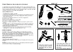
8. Routing the wires
Confirm that hoses and wires are routed in
order starting from front to back
front brake hose
1
rear brake hose
2
dropper seat wire
3
shift wire
4
compact multifunction meter lead
5
switch unit lead
6
Clamp the front brake hose
1
and rear brake
hose
2
with the wire clip
7
at the position
shown in the illustration.
Clamp the front brake hose
1
and dropper seat
wire
3
with the wire clip
8
at the position
shown in the illustration.
Clamp the front brake hose
1
and switch unit
lead
6
with the wire clip
9
at the position
shown in the illustration.
Clamp the dropper seat wire
3
and shift wire
4
with the wire clip
0
at the position shown in the
illustration.
Clamp the dropper seat wire
3
and compact
multifunction meter lead
5
with the plastic lock-
ing ties
q
at the position shown in the illustra-
tion.
Secure the front brake hose
1
with the wire
clamp
w
at the position shown in the illustra-
tion.
1
2
3
4
5
6
7
8
9
0
q
w
Be sure to route the wires as shown in the illus-
tration. If not, they could interfere with handle-
bar operation which could cause loss of
control.
WARNING
X1V-28107-10.book 9 ページ 2020年8月3日 月曜日 午後4時11分
Summary of Contents for PB65ML
Page 5: ...INCLUDED PARTS 3 7 9 1 2 3 4 5 0 w 7 8 9 q e r t 6 y ...
Page 20: ......


