3-47
1
2
3
4
5
6
7
8
9
10
ENGINE
PISTONS, CAMSHAFT, CRANKCASE, AND CRANKSHAFT
TIP
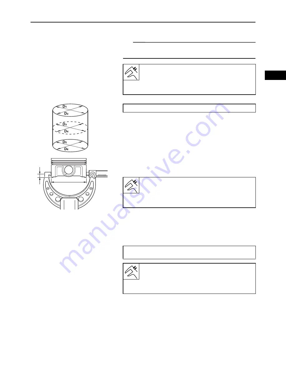
Measure cylinder bore “C” by taking side-to-side and front-
to-back measurements of the cylinder.
b. If out of specification, replace the crankcase
assembly, and replace the piston and piston rings
as a set.
c. Measure piston skirt diameter “P” with the microm-
eter.
a = 5.1 mm (0.2007 in) from the piston bottom edge
d. If out of specification, replace the piston and piston
rings as a set.
e. Calculate the piston-to-cylinder clearance with the
following formula.
f. If out of specification, replace the crankcase
assembly, and replace the piston and piston rings
as a set.
▲▲▲▲▲▲▲▲▲▲▲▲▲▲▲▲▲▲▲▲▲▲▲▲▲▲▲▲▲▲▲▲▲▲▲▲▲▲▲▲▲
Bore:
80.000–80.020 mm (3.1496–3.1504 in)
Warpage limit:
80.025 mm (3.1506 in)
“C” = maximum of D
1
, D
2
, D
3
, D
4
, D
5
, D
6
P
a
Piston diameter:
79.959–79.980 mm (3.1480–3.1488 in)
Limit:
79.900 mm (3.1457 in)
Piston-to-cylinder clearance = Cylinder bore “C” – Piston skirt
diameter “P”
Piston-to-cylinder clearance:
0.033–0.047 mm (0.0013–0.0019 in)
Limit:
0.15 mm (0.0059 in)
Summary of Contents for MX800V
Page 2: ...7UC F8197 E0_Hyoshi indd 3 4 2017 10 27 13 08 23 ...
Page 38: ...2 18 1 2 3 4 5 6 7 8 9 10 PERIODIC CHECKS AND ADJUSTMENTS PERIODIC MAINTENANCE MEMO ...
Page 94: ...3 56 1 2 3 4 5 6 7 8 9 10 ENGINE PISTONS CAMSHAFT CRANKCASE AND CRANKSHAFT MEMO ...
Page 103: ...4 9 1 2 3 4 5 6 7 8 9 10 FUEL INTAKE MANIFOLD MEMO ...
Page 106: ...5 3 1 2 3 4 5 6 7 8 9 10 ELECTRICAL ELECTRICAL COMPONENTS ELECTRICAL COMPONENTS 1 3 4 5 2 2 ...
Page 118: ...5 15 1 2 3 4 5 6 7 8 9 10 ELECTRICAL ELECTRIC STARTING SYSTEM MEMO ...
Page 140: ...7 14 1 2 3 4 5 6 7 8 9 10 SPECIFICATIONS WIRE ROUTING DIAGRAM ...
Page 142: ...7 16 1 2 3 4 5 6 7 8 9 10 SPECIFICATIONS WIRE ROUTING DIAGRAM LEFT SIDE VIEW ...
Page 144: ...7 18 1 2 3 4 5 6 7 8 9 10 SPECIFICATIONS WIRE ROUTING DIAGRAM RIGHT SIDE VIEW ...
Page 146: ...7 20 1 2 3 4 5 6 7 8 9 10 SPECIFICATIONS WIRE ROUTING DIAGRAM ...
Page 148: ...7 22 1 2 3 4 5 6 7 8 9 10 SPECIFICATIONS WIRE ROUTING DIAGRAM ...
Page 150: ...7 24 1 2 3 4 5 6 7 8 9 10 SPECIFICATIONS WIRE ROUTING DIAGRAM REAR SIDE VIEW ...
Page 152: ...7 26 1 2 3 4 5 6 7 8 9 10 SPECIFICATIONS WIRE ROUTING DIAGRAM ...
Page 156: ...MEMO ...
Page 157: ...7UC F8197 E0_Hyoshi indd 3 4 2017 10 27 13 08 23 ...


