


2-6
1
2
3
4
5
6
7
8
9
10
PE
RIODIC
CHE
CKS AND ADJUSTMENTS
PERIODIC MAINTENANCE
3.
Install:
• Oil filler cap
TIP
Check whether the oil warning light comes on by turning
the main switch.
Oil warning light comes on
Add oil.
Oil warning light does not comes on
OK.
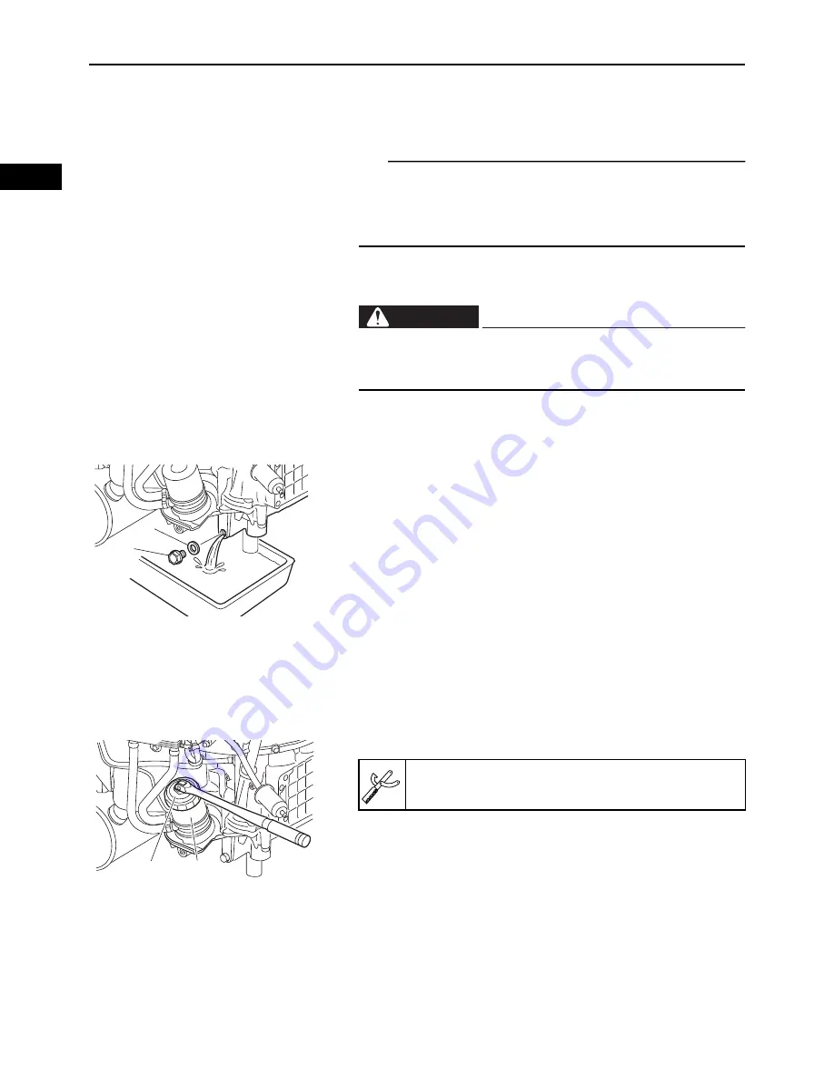
REPLACING THE ENGINE OIL
1.
Warm up the engine for several minutes, and then
stop the engine.
Place the oil pan under the engine.
2.
Remove:
• Oil filler cap
• Oil drain bolt “1”
• Oil drain bolt gasket “2”
3.
Drain:
• Engine oil
4.
If the oil filter is also to be replaced, perform the fol-
lowing procedure.
▼▼▼▼▼▼▼▼▼▼▼▼▼▼▼▼▼▼▼▼▼▼▼▼▼▼▼▼▼▼▼▼▼▼▼▼▼▼▼▼▼
a. Remove the oil filter “1” with an oil filter wrench “2”.
Avoid draining the engine oil immediately after stop-
ping the engine. The oil is hot and should be handled
with care to avoid burns.
WARNING
1
2
2
1
Oil filter wrench:
YM-01469
Summary of Contents for MX800V
Page 2: ...7UC F8197 E0_Hyoshi indd 3 4 2017 10 27 13 08 23 ...
Page 38: ...2 18 1 2 3 4 5 6 7 8 9 10 PERIODIC CHECKS AND ADJUSTMENTS PERIODIC MAINTENANCE MEMO ...
Page 94: ...3 56 1 2 3 4 5 6 7 8 9 10 ENGINE PISTONS CAMSHAFT CRANKCASE AND CRANKSHAFT MEMO ...
Page 103: ...4 9 1 2 3 4 5 6 7 8 9 10 FUEL INTAKE MANIFOLD MEMO ...
Page 106: ...5 3 1 2 3 4 5 6 7 8 9 10 ELECTRICAL ELECTRICAL COMPONENTS ELECTRICAL COMPONENTS 1 3 4 5 2 2 ...
Page 118: ...5 15 1 2 3 4 5 6 7 8 9 10 ELECTRICAL ELECTRIC STARTING SYSTEM MEMO ...
Page 140: ...7 14 1 2 3 4 5 6 7 8 9 10 SPECIFICATIONS WIRE ROUTING DIAGRAM ...
Page 142: ...7 16 1 2 3 4 5 6 7 8 9 10 SPECIFICATIONS WIRE ROUTING DIAGRAM LEFT SIDE VIEW ...
Page 144: ...7 18 1 2 3 4 5 6 7 8 9 10 SPECIFICATIONS WIRE ROUTING DIAGRAM RIGHT SIDE VIEW ...
Page 146: ...7 20 1 2 3 4 5 6 7 8 9 10 SPECIFICATIONS WIRE ROUTING DIAGRAM ...
Page 148: ...7 22 1 2 3 4 5 6 7 8 9 10 SPECIFICATIONS WIRE ROUTING DIAGRAM ...
Page 150: ...7 24 1 2 3 4 5 6 7 8 9 10 SPECIFICATIONS WIRE ROUTING DIAGRAM REAR SIDE VIEW ...
Page 152: ...7 26 1 2 3 4 5 6 7 8 9 10 SPECIFICATIONS WIRE ROUTING DIAGRAM ...
Page 156: ...MEMO ...
Page 157: ...7UC F8197 E0_Hyoshi indd 3 4 2017 10 27 13 08 23 ...


