background image

Front & Rear Panels

MW10 Owner's Manual

16

English

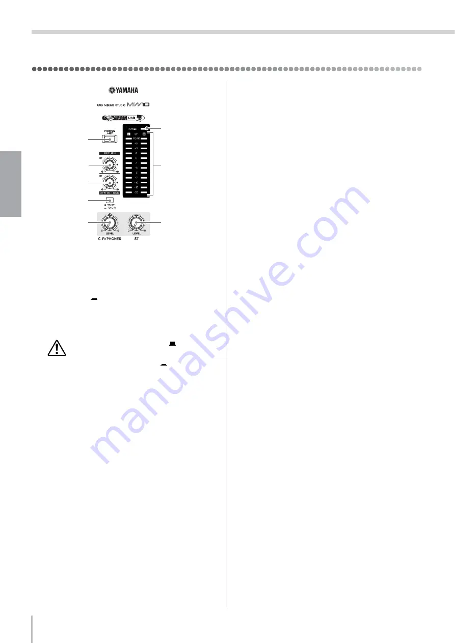
Master Control Section

1

P48 V Switch

This switch toggles phantom power on and off. If you set 
the switch on, the mixer supplies power to all channels 
that provide XLR mic input jacks (CHs 1, 2, 3/4, 5/6). Set 
this switch on (

) when using one or more condenser 

microphones. 

n

When this switch is on, the mixer supplies DC +48 V 
power to pins 2 and 3 of all XLR-type MIC INPUT jacks.

• Be sure to leave this switch off (

) if you do not 

need phantom power.

• When tuning the switch on (

), be sure that 

only condenser mics are connected to the XLR 
input jacks (CHs: 1 to 5/6). Devices other than 
condenser mics may be damaged if connected to 
the phantom power supply. Note, however, that 
the switch may be left on without problem when 
connecting to balanced dynamic microphones. 

• To avoid damage to speakers, be sure to turn off

amplifiers (or powered speakers) before turning
this switch on or off. We also recommend that you
turn all output controls (ST Master LEVEL Con-
trol, etc.) to minimum settings before operating
the switch, to avoid risk of loud noises that could
cause hearing loss or device damage.

2

RETURN Control

Adjusts the level of the signal sent from the RETURN 
jacks (L (MONO) and R) to the Stereo bus.

n

If you supply a signal to the RETURN L (MONO) jack 
only, the mixer outputs the identical signal to both the L 
and R Stereo buses.

3

2TR IN/USB Control

Adjusts the level of signals received via 2TR IN, as well 
as the level of signals received by the MW10 from the 
computer via the USB interface.

4

2TR IN/USB Switch (TO ST/TO C-R)

Determines whether the stereo signal received via the 
2TR IN connectors or USB interface is sent to the stereo 
bus or the C-R OUT connectors and PHONES jack (level 
meter).

n

• When the 2TR IN/USB switch is set to TO ST, the 

signal input via the 2TR IN/USB connector is added 
to the stereo bus.

• When the 2TR IN/USB switch is set to TO C-R, the 

signal input via the 2TR IN/USB connector is directly 
sent to the C-R OUT/PHONES connector, and is not 
output via the stereo bus.

5

ST Master LEVEL Control

Adjusts the signal level to the ST OUT jacks.

6

C-R/PHONES LEVEL Control

Controls the level of the signal output to the PHONES 
jack and the C-R OUT L and R jacks.

7

Level Meter

This LED display shows the level of the signal fed to the 
Stereo bus. The “0” point corresponds to the standard 
output level. The indicator lights up red when the output 
hits the clipping level.

8

POWER Indicator

This indicator lights up when the mixer’s power is ON.

8

7

1

5

2

3
4

6

Summary of Contents for MW10

Page 1: ......

Page 2: ...other product use only high quality shielded cables Cable s supplied with this product MUST be used Follow all installation instructions Failure to follow instructions could void your FCC authorization to use this product in the USA 3 NOTE This product has been tested and found to comply with the requirements listed in FCC Regulations Part 15 for Class B digital devices Compliance with these requi...

Page 3: ...ns include but are not limited to the following Remove the electric plug from the outlet when the device is not to be used for extended periods of time or during electrical storms When removing the electric plug from the device or an outlet always hold the plug itself and not the cord Pulling by the cord can damage it To avoid generating unwanted noise make sure there is 50 cm or more between the ...

Page 4: ...hich appear on your computer The illustrations as shown in this owner s manual are for instructional purposes only and may appear somewhat different from those on your device This product incorporates and bundles computer programs and contents in which Yamaha owns copyrights or with respect to which it has license to use others copyrights Such copyrighted materials include without limitation all c...

Page 5: ...e 7 Cubase LE software included in the MW10 package offers versatile high performance hard disk recording capability 3 Band EQ On Each Channel page 15 Each channel of the MW10 mixer features full 3 band equalization providing broad musical response shaping capability Mixer Functions page 15 With up to four mic line inputs or up to four stereo inputs the MW10 can simultaneously connect to a wide ra...

Page 6: ...again for a long while please be sure to unplug the adaptor from the wall outlet n To prevent loud pops and noises turn on the power to your sound gear starting with the sources instruments CD players etc and ending with the power amplifier or powered speakers Example Instruments microphones and CD players first then the mixer and finally the power amplifier or powered speakers When turning off th...

Page 7: ...n making connections refer to the Input Output section on page 17 and the Setting up section on page 20 Step 1 Installing Cubase LE Step 2 Connections USB Connection Precautions Be sure to observe the following points when connecting to the computer s USB interface Failure to observe these rules can result in computer freezes hang ups and possibly data loss or corruption If the computer or MW10 do...

Page 8: ... to externally induced noise and is used primarily for balanced connections With properly designed receiving circuitry cables with this type of connector can also be used for unbalanced signals XLR type connectors are the standard for microphone connections as well as most professional audio gear Phone Connectors Phone connectors are available in mono and stereo versions Stereo types are also know...

Page 9: ...tep 4 Adjusting Level and Equalization LEVEL Control ST Master LEVEL Control C R PHONES Control GAIN Control PEAK Indicator Use the High pass Filter for Microphone Input As the name implies a high pass filter allows only signals above a certain frequency to pass Conversely signals below that cutoff frequency are attenuated When an MW10 high pass filter is turned on signals below 80 Hz are attenuat...

Page 10: ...ubase LE software launch the application from that location Create a Cubase LE shortcut or Alias on your desktop so you can easily launch the program when required 3 Select Device Setup from the Devices menu to open the Device Setup window Windows Select VST Multitrack in the Devices field on the left side of the window Select ASIO Multimedia Driver in the ASIO Driver field on the right side of th...

Page 11: ...n For this example select 24 Track Audio Recorder and click OK n Recorded Cubase LE data is stored as a project file for each song 9 When the directory selection dialog window appears select the folder to which the project and audio files for the project are to be stored and click OK An empty 24 audio track project window will appear Preparing to Record 1 Click in the track list the area in which ...

Page 12: ...level meter while the Record Enable button is on 5 Play the instrument to be recorded and while watching the mixer window level meter adjust the MW10 GAIN controls Channel LEVEL Controls and ST Master LEVEL Control so that the meter never goes above 0 0 dB n The Cubase LE channel strip fader only affects the playback output level from Cubase LE The maximum level encountered is displayed numericall...

Page 13: ... to audio CDs 1 Launch Cubase LE and open a project file 2 Select Mixer from the Devices menu to open the mixer window 3 Turn the Record Enable buttons for all recorded tracks off in order to display the corresponding levels via the channel strip levels meters 4 Click the Transport panel Play button 5 Drag the channel strip faders up and down while listening to playback to adjust the mix as requir...

Page 14: ...he mixdown operation will be shown in a progress window When the progress window closes the mixdown is complete n Wave files created by mixdown can be directly playback back using the Windows Media Player or iTunes on a Macintosh computer Pan Effectively Panning creates the illusion of stereo space by changing the relative levels of each track s signal sent to the left and right speakers If a sign...

Page 15: ...the sound to be shaped as required by the mix 5 AUX Controls Use the AUX control to send the channel s signal to the AUX1or AUX2 bus Turn the knob to the left of the mark to feed the signal to the AUX1 bus or to the right of the to feed to the AUX2 bus The volume of the feed increases as you move the knob away from the position If you set the knob exactly to the position the mixer will not send th...

Page 16: ...he level of the signal sent from the RETURN jacks L MONO and R to the Stereo bus n If you supply a signal to the RETURN L MONO jack only the mixer outputs the identical signal to both the L and R Stereo buses 3 2TR IN USB Control Adjusts the level of signals received via 2TR IN as well as the level of signals received by the MW10 from the computer via the USB interface 4 2TR IN USB Switch TO ST TO...

Page 17: ... be aware of possible phase conflicts with other signals 3 Channel Input Jacks CHs 7 8 9 10 Each of these channel pairs can be used to input a stereo source signal For each pair the odd numbered channel inputs the L signal and the even numbered channel inputs the R signal Each channel offers a choice of two jack types phone jack and RCA pin jack All of these jacks are unbalanced n Where a channel ...

Page 18: ...N L MONO R Jacks These are unbalanced phone type input jacks The signal received by these jacks is sent to the Stereo bus These jacks are typically used to receive a return signal from an external effector reverb delay etc n These jacks can also be used as an auxiliary stereo input If you connect to the L MONO jack only the mixer will recognize the signal as monaural and will propagate the identic...

Page 19: ...tric shock 2 POWER Switch Use this switch to set mixer power to ON or STANDBY Note that trace current continues to flow while the switch is in the STANDBY position If you do not plan to use the mixer again for a long while be sure to unplug the adaptor from the wall outlet 3 USB Connector Connects to the computer via the supplied USB cable When connecting or disconnecting the USB cable be sure to ...

Page 20: ...ovides both a MIC INPUT jack and a LINE INPUT jack you may use either one of these jacks but you may not use both at the same time Please connect to only one of these jacks on each channel 3 To avoid causing damage to speakers power up the devices in the following order Peripheral devices mixer power amps or powered speakers n When shutting the system down turn off the power in the opposite order ...

Page 21: ... input select USB Audio CODEC 3 Click the Output tab and under Choose a device for sound output select USB Audio CODEC Is the sound output of the Cubase LE application assigned properly For setup details refer to page 10 of the Quick Guide The recorded sound is too low in level Is the computer s output level setting too low We recommend that you set the computer output to the maximum level Windows...

Page 22: ...to Good Don t change these settings if you are not familiar with your computer s operating system Check that the file system is set properly and make sure that you have a plenty of free memory more than 128 MB If the wave files you are recording or playing are not too large changing the virtual memory settings can sometimes improve audio performance In some cases it might be necessary to update yo...

Page 23: ...m level 76 dB CH INPUT 1 5 6 MIC to REC OUT Rs 150 ohms GAIN controls at maximum level 64 2 dB CH INPUT 1 2 MIC to AUX SEND Rs 150 ohms GAIN controls at maximum level PRE 70 dB CH INPUT 1 2 MIC to AUX SEND Rs 150 ohms GAIN controls at maximum level POST 76 dB CH INPUT 3 4 5 6 LINE to ST OUT Rs 150 ohms GAIN controls at maximum level 50 dB CH INPUT 3 4 5 6 LINE to AUX SEND Rs 150 ohms GAIN controls...

Page 24: ... unbal anced 10 2 dBu 0 615 V 10 dBu 2 45 V 30 dBu 24 5 V ST CH INPUT CH7 L CH8 R CH9 L CH10 R 10 k ohms 600 ohms line 22 dBu 61 5 mV 10 dBu 245 mV 10 dBu 2 45 V Phone jack unbal anced RCA pin jack CH INSERT IN CH 1 2 10 k ohms 600 ohms line 12 dBu 195 mV 0 dBu 0 775 V 20 dBu 7 75 V Phone jack TRS unbalanced T out R in S ground RETURN L R 10 k ohms 600 ohms line 8 dBu 308 mV 4 dBu 1 23 V 24 dBu 12...

Page 25: ...Appendix MW10 Owner s Manual 25 Dimensional Diagrams Unit mm 251 290 5 65 English Deutsch Français Español ...

Page 26: ...Appendix MW10 Owner s Manual 26 Block Diagram and Level Diagram English Deutsch Français Español ...

Page 27: ...FTWARE are subject to the following restrictions which you must observe Data received by means of the SOFTWARE may not be used for any commercial purposes without permission of the copyright owner Data received by means of the SOFTWARE may not be duplicated transferred or distributed or played back or performed for listeners in public without permission of the copyright owner The encryption of dat...

Page 28: ...or your use thereof Yamaha provides no express warranties as to the THIRD PARTY SOFTWARE IN ADDITION YAMAHA EXPRESSLY DISCLAIMS ALL IMPLIED WARRANTIES INCLUDING BUT NOT LIMITED TO THE IMPLIED WARRANTIES OF MERCHANTABILITY AND FITNESS FOR A PARTICULAR PURPOSE as to the THIRD PARTY SOFTWARE Yamaha shall not provide you with any service or maintenance as to the THIRD PARTY SOFTWARE Yamaha is not liab...

Page 29: ...ie dürfen nicht die SOFTWARE verwenden um illegale oder gegen die guten Sitten verstoßende Daten zu verbreiten Sie dürfen nicht auf dem Gebrauch der SOFTWARE basierende Dienstleistungen erbringen ohne die Erlaubnis der Yamaha Corporation Urheberrechtlich geschützte Daten einschließlich aber nicht darauf beschränkt MIDI Songdateien die mithilfe dieser SOFTWARE erstellt werden unterliegen den nachfo...

Page 30: ... SOFTWARE DRITTER bezeichnet wird erkennen Sie die Bestimmungen aller mit der SOFTWARE DRITTER mitgelieferten Vereinbarungen an und erkennen an dass der Hersteller der SOFTWARE DRITTER verantwortlich ist für etwaige Garantien oder Haftungen für die SOFTWARE DRITTER Yamaha ist in keiner Weise verantwortlich für die SOFTWARE DRITTER oder deren Gebrauch durch Sie Yamaha gibt keine ausdrücklichen Zusi...

Page 31: ...e ce LOGICIEL sont soumises aux restrictions suivantes que vous devez impérativement respecter Les données reçues au moyen de ce LOGICIEL ne peuvent en aucun cas être utilisées à des fins commerciales sans l autorisation du propriétaire du droit d auteur Les données reçues au moyen de ce LOGICIEL ne peuvent pas être dupliquées transférées distribuées reproduites ou exécutées devant un public d aud...

Page 32: ...GICIELS DE FABRICANTS TIERS ou de l utilisation que vous en faites Yamaha exclut toute garantie expresse portant sur des LOGICIELS DE FABRICANTS TIERS DE SURCROIT YAMAHA EXCLUT EXPRESSEMENT TOUTE RESPONSABILITE IMPLICITE LIEE AU LOGICIEL DE FABRICANT TIERS Y COMPRIS DE MANIERE NON LIMITATIVE TOUTE GARANTIE IMPLICITE DE QUALITE MARCHANDE ET D ADEQUATION A UN USAGE PARTICULIER LE CONCERNANT Yamaha n...

Page 33: ...TWARE está sometida a las restricciones que se indican a continuación y que el usuario debe acatar La información recibida mediante el SOFTWARE no podrá utilizarse para fines comerciales sin autorización del propietario del copyright La información recibida mediante el SOFTWARE no puede duplicarse transferirse ni distribuirse ni reproducirse ni interpretarse para ser escuchada en público sin autor...

Page 34: ...RAS MARCAS ni del uso que usted haga de él Yamaha no ofrece garantías expresas con respecto al SOFTWARE DE OTRAS MARCAS ADEMÁS YAMAHA DENIEGA EXPRESAMENTE TODAS LAS GARANTÍAS IMPLÍCITAS INCLUIDAS SIN LIMITACIONES LAS GARANTÍAS IMPLÍCITAS DE COMERCIABILIDAD E IDONEIDAD PARA UNA FINALIDAD DETERMINADA con respecto al SOFTWARE DE OTRAS MARCAS Yamaha no prestará ningún servicio ni mantenimiento para el...

Page 35: ...47 Skiathou Street 112 55 Athens Greece Tel 01 228 2160 SWEDEN Yamaha Scandinavia AB J A Wettergrens Gata 1 Box 30053 S 400 43 Göteborg Sweden Tel 031 89 34 00 DENMARK YS Copenhagen Liaison Office Generatorvej 6A DK 2730 Herlev Denmark Tel 44 92 49 00 FINLAND F Musiikki Oy Kluuvikatu 6 P O Box 260 SF 00101 Helsinki Finland Tel 09 618511 NORWAY Norsk filial av Yamaha Scandinavia AB Grini Næringspar...

Page 36: ...Corporation WG35780 606MWZCx x 0xB0 Printed in Indonesia Yamaha Web Site English only http www yamahasynth com Yamaha Manual Library http www yamaha co jp manual Track Sheet Source Source Source Source Source Source Source Source Mixer Setup Title Date Place Notes Session Information ...

Reviews: