6
■
Connectors
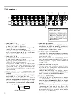
INPUT A
INPUT B
OUT IN
INPUT CH INSERT I/O 0dB
OUT IN
1
2
3
4
5
6
7
8
1
2
3
4
5
6
7
8
–10dB
R
R
L
L
1R
1L/MONO
2R
2L/MONO
3
1
4
2
L
R
+4dB
–10dB
TAPE IN
REC OUT
STEREO OUT +4dB
AUX 4dB
AUX SEND +4dB
MONO OUT
1
2
3
4
5
6
7
8
1
2
3
4
5
6
7
8
9
MICROPHONE CABLES AND
MICROPHONES CONNECTION
TO PREVENT HAZARD OR DAMAGE,
ENSURE THAT ONLY MICROPHONE
CABLES AND MICROPHONES
DESIGNED TO THE IEC268-15A
STANDARD ARE CONNECTED.
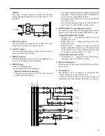
In this case, the final output level is adjusted by the REC
OUT control (master control section
9
), and the STEREO
L,R fader settings will have no affect.
6
STEREO OUT (L, R)
This is the stereo output of the combined audio signals.
Connect these jacks to the power amp that drives your
main speakers.
Alternatively, you can record the output from these jacks if
you wish to use the STEREO L,R faders to adjust the audio
level being recorded.
7
MONO OUT
This is the MONO OUT output jack. The MONO OUT can
be used for simple recordings of a live performance, for
driving a sub power amp, or to check for phase
cancellation.
An internal jumper can be reconnected to change the
location of the MONO OUT to post-ST fader. If this is
done, the MONO OUT signal will be affected by the STE-
REO ON switch.
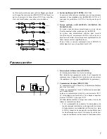
Internal jumper wires can be changed to move the MONO
OUT signal so that it is taken after the ST fader. If you would
like this change to be made, consult with your dealer.
ON
ON
R
L
STEREO OUT
MONO OUT
INV
INV
SUM
SUM
SUM
INV
INV
ON
ON
R
L
STEREO OUT
MONO OUT
INV
INV
SUM
SUM
SUM
1
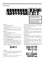
INPUT A
These are XLR type connectors.
(1: sleeve, 2: hot, 3: cold)
Microphones of 50–600
Ω
or 600
Ω
line level devices can
be connected here.
When the PHANTOM switch (rear panel
2
) is turned on,
DC+48V will be supplied to pins 2 and 3 of these connectors.
2
INPUT B
These are balanced phone connectors.
(T: hot, R: cold, S: sleeve)
Microphones of 50–600
Ω
or 600
Ω
line level devices can
be connected here.
Unbalanced phone plugs can also be connected, however,
noise may occur with long cables, or cables subjected to strong
electromagnetic fields caused by radio and TV broadcasts.
3
INPUT CH INSERT I/O 0dB
These are input/output jacks located between the head amp
and the equalizer of the input channel section.
The nominal input level and impedance is 0dB/600
Ω
, and
the nominal output level and impedance is 0dB/10k
Ω
.
These jacks allow you to insert your own graphic
equalizers, compressors, noise filters, or other devices.
INSERT OUT
INSERT IN
4
TAPE IN
Your DAT or cassette deck can be directly connected here
for convenient monitoring. Use the TAPE IN control
(master control section
0
) to adjust the level.
5
REC OUT
Your DAT or cassette deck can be connected here to
record the audio signal from STEREO OUT.


