65
RX-V381/HTR-3069
RX-V381/HTR-3069
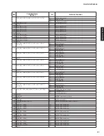
No.
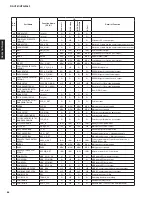
Function Name
(P.C.B.)
I/O
Detail of Function
12
8
DVDD
12
9
A
H
CL
K
R0/GP2[14
]
/BOOT[11
]
I/O
McASP0 receive master clock
I
BOOT[11
]
1
3
0 ACL
K
R0/ECAP1/APWM1/GP2[1
5]
I/O
McASP0 receive bit clock
I/O
Enhanced capture 1 input or auxiliary PWM 1 output
1
3
1 AFSR0/GP
3
[12
]
I/O
McASP0 receive frame sync
1
3
2 AMUTE1/EPWMTZ/GP4[14
]
I/O
McASP1 mute output
I/O
e
H
RPWM0 trip zone input
I/O
e
H
RPWM1 trip zone input
I/O
e
H
RPWM2 trip zone input
1
33
RSV2
PWR
Reserved. For proper device operation, this pin must be tied directly to
CVDD or left unconnected [do not connect to ground (VSS)
]
.
1
3
4 USB0_VDDA12
PWR
USB0 P
H
Y 1.2-V LDO output for bypass cap
1
35
USB0_VDDA1
8
PWR
USB0 P
H
Y 1.
8
-V supply input
1
36
NC
-
-
1
3
7 USB0_DP
A
USB0 P
H
Y data plus
1
38
USB0_DM
A
USB0 P
H
Y data minus
1
39
NC
-
-
140 USB0_VDDA
33
PWR
USB0 P
H
Y
3
.
3
-V supply
141 PLL0_VDDA
PWR
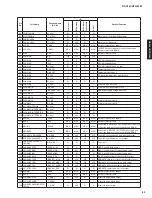
PLL analog VDD (1.2-V filtered supply)
142 PLL0_VSSA
GND
PLL analog VSS (for filter)
14
3
OSCIN
I
Oscillator input
144 OSCVSS
GND
Oscillator ground (for filter only)
14
5
OSCOUT
O
Oscillator output
14
6
RESET
I
Device reset input
147 CVDD
14
8
RTC_XI
I
Low-frequency (
3
2-k
H
z) oscillator receiver for real-time clock
14
9
RTC_CVDD
PWR
RTC module core power ( isolated from rest of chip CVDD)
1
5
0 TRST
I
J
TAG test reset
1
5
1 DVDD
1
5
2 TMS
I
J
TAG test mode select
1
53
TDI
I
J
TAG test data input
1
5
4 CVDD
1
55
TC
K
I
J
TAG test clock
1
56
TDO
O
J
TAG test data output
1
5
7 GP7[14
]
I/O
General-Purpose IO signal
1
58
DVDD
1
59
CVDD
1
6
0 A
H
CL
K
X1/EPWM0B/GP
3
[14
]
I/O
McASP1transmit master clock
I/O
e
H
RPWM0 B output
1
6
1 CVDD
1
6
2 ACL
K
X1/EPWM0A/GP
3
[1
5]
I/O
McASP1transmit bit clock
I/O
e
H
RPWM0 A output
1
63
AFSX1/EPWMSYNCI/EPWMSYNCO/GP4[10
]
I/O
McASP1transmit frame sync
I/O
Sync input to e
H
RPWM0 module or sync output to external PWM
1
6
4 DVDD
1
65
ACL
K
R1/ECAP2/APWM2/GP4[12
]
I/O
McASP1receive bit clock
I/O
Enhanced capture 2 input or auxiliary PWM 2 output
1
66
AFSR1/GP4[1
3]
I/O
McASP1receive frame sync
1
6
7 CVDD
1
68
AXR1[
8]
/EPWM1A/GP4[
8]
I/O
McASP1 serial data
I/O
e
H
RPWM1 A output (with high-resolution)
1
69
AXR1[7
]
/EPWM1B/GP4[7
]
I/O
McASP1 serial data
I/O
e
H
RPWM1 B output
170 AXR1[
6]
/EPWM2A/GP4[
6]
I/O
McASP1 serial data
I/O
e
H
RPWM2 A output (with high-resolution)
171 AXR1[
5]
/EPWM2B/GP4[
5]
I/O
McASP1 serial data
I/O
e
H
RPWM2 B output
172 DVDD
17
3
AXR1[4
]
/EQEP1B/GP4[4
]
I/O
McASP1 serial data
I
eQEP1B quadrature input
174 AXR1[
3]
/EQEP1A/GP4[
3]
I/O
McASP1 serial data
I
eQEP1A quadrature input
17
5
AXR1[2
]
/GP4[2
]
I/O
McASP1 serial data
17
6
AXR1[1
]
/GP4[1
]
I/O
McASP1 serial data
Summary of Contents for HTR-3069
Page 6: ...6 RX V381 HTR 3069 RX V381 HTR 3069 RX V381 K model RX V381 A model RX V381 B model ...
Page 7: ...7 RX V381 HTR 3069 RX V381 HTR 3069 RX V381 G F models RX V381 L model RX V381 S model ...
Page 8: ...8 RX V381 HTR 3069 RX V381 HTR 3069 RX V381 J model HTR 3069 U C models HTR 3069 T model ...
Page 9: ...9 RX V381 HTR 3069 RX V381 HTR 3069 HTR 3069 K model HTR 3069 B model TR 3069 G F models ...
Page 10: ...10 RX V381 HTR 3069 RX V381 HTR 3069 HTR 3069 L model ...
Page 138: ...RX V379 HTR 3068 ...

