– 3 –
Power generation
Stage 1. The rectifier circuit converts three-phase AC into DC and it maintains stable DC voltage using a con-
stant voltage circuit
Stage 2. The Constant voltage DC current is stored in a condenser.
Stage 3. The PWM, pulse width modulator, inverter circuit generates a stable sine wave AC current.
Stage 4. The filter circuit further smoothen the sine wave of the AC current and reduce electrical noise.
Protective functions:
■
Overload (over current) protection device
The control unit has similar function to conventional NFB. When the output current exceeds specified
amperage, AC output is interrupted within specified length of time.
■
Overheat protection
When the internal temperature of the control unit becomes abnormally high, AC output is interrupted.
■
Over-voltage protection device
AC output is interrupted when the excessive current flows into the generator from outside power source
causing to rise voltage in the control unit.
Other functions of control unit:
Throttle control............... Control unit commands throttle motor to adjust engine speed automatically in
accordance with the amount of the electrical consumption.
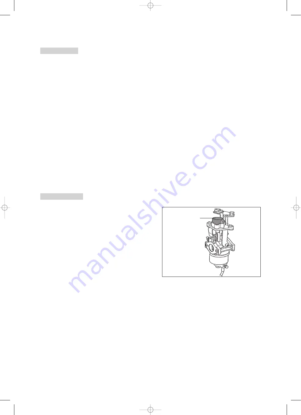
Electronic governor
An electronic governor takes the place of a convention-
al mechanical governor, and opens and closes the car-
buretor throttle valve electrically.
Components and functions:
■
Inverter control unit
The control unit constantly monitors the AC output
from the control unit, and adjusts the throttle motor to
produce the necessary engine speed.
■
Throttle motor (stepping motor)
The throttle motor receives pulses from the control unit
and opens or closes the throttle valve approximately 0.7
degrees per pulse.
Stepping motor
EF3000iSE new model guide 3/14/03 4:20 PM Page 3


