background image

26

E

N

G

L

IS

H

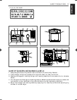
PRE-OPERATION CHECK

8

 Keep  all  sparks  and  flames 

away  from  the  battery  and  fuel 

tank.  A  battery,  especially  when 

charging,  will  give  off  hydrogen 

and  oxygen  gases  which  can 

explode  and  cause  serious 

personal injury.

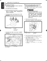
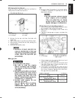
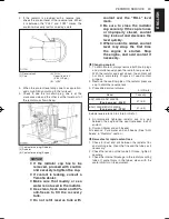
1.  Remove the vent plugs.

2.  Fill cells up to the upper level with electrolyte.


[Specific gravity of sulfuric acid 1.270 to 1.290 (at 

20°C = 68°F)]

3.  Allow  the  battery  to  sit  for  about  one  hour  after 

filling.

4.  If  the  electrolyte  level  is  dropped,  refill  with 

electrolyte up to the upper level.

5.  Replace the vent plugs.

6.  Charge the battery at the normal charging rate of 

6.0 amperes.

7.  Wash off any electrolyte which may have spilled.

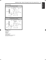
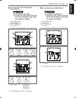
(1)  Vent plug opening
(2) Electrolyte level indication 

tube

(3) Indicated level

(A) Upper level
(B) Lower level

TIP

8

  The duration of dry charged efficiency, will decrease 

in  proportion  to  the  period  of  time  elapsed  after 

shipment and during storage. To obtain the longest 

service  life  of  the  battery,  it  is  necessary  for  the 

battery to be charged for a sufficient period of time. 

Continue to charge until all cells are gassing freely, 

and the voltage and specific gravity reading in all 

cells  remain  constant  for  3  or  more  successive 

readings taken at 30 minute intervals.

8

  When  the  battery  has  been  charged  fully,  the 

specific  gravity  of  electrolyte  should  be  1.270  to 

1.290 (at 20°C = 68°F).


‹

Engine oil

The  generator  has  been  shipped  without  engine 

oil.  Fill  with  oil  to  the  correct  level  before 

attempting to start the engine.

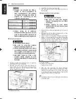
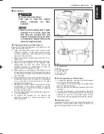
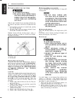
1.  Place the machine on a level surface.

2.  Remove the oil cap.

3.  Add  engine  oil  of  grade  CD  or  higher,  up  to  the 

upper mark on the oil level gauge.

TIP

8

  See “Engine Oil” in “PERIODIC SERVICE” section 

for  engine  oil  capacity  and  checking  engine  oil 

level.


‹

Coolant

WARNING

To avoid personal injury:

8

 Place  the  machine  on  a  level 

surface.

8

 DO  NOT  remove  the  radiator 

cap while coolant is hot. When 

cool,  rotate  the  radiator  cap 

slowly to the first stop to allow 

excess  pressure  to  escape. 

Then remove cap completely.

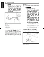
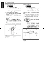
1.  Remove  the  radiator  cap  and  fill  with  specified 

coolant until the coolant level is just below the port.

2.  Fill with coolant to the “FULL” mark on the reserve 

tank.

3.  Securely  tighten  radiator  cap  and  reserve  tank 

cap.

TIP

8

  See  “Radiator”  in  “PERIODIC  SERVICE”  section 

for changing coolant.

9CN-9-U1-E0.indd   31

2013/11/19   13:50:53

Summary of Contents for EDL11000SDE

Page 1: ...s de utilizar este equipo Leia este manual cuidadosamente antes de conduzir a máquina Прочтите данное руководство внимательно и полностью до эксплуатации этого оборудования Baca buku petunjuk ini secara teliti sebelum mengoperasikan mesin OWNER S MANUAL MANUEL D UTILISATION MANUAL DEL PROPIETARIO MANUAL DO PROPRIETÁRIO РУКОВОДСТВО ПОЛЬЗОВАТЕЛЯ BUKU PETUNJUK PENGGUNAAN ENGLISH FRANÇAIS ESPAÑOL PORT...

Page 2: ......
Page 3: ...ENGLISH EDL7000SE EDL7000SDE EDL11000SE EDL11000SDE 9CN 28199 U1 E0 OWNER S MANUAL Read this manual carefully before operating this machine ...

Page 4: ...ENGLISH Read this manual carefully before operating this machine This manual should stay with this machine if it is sold ...
Page 5: ... any questions regarding the operation or maintenance of your machine please consult a Yamaha dealer EDL7000SE EDL7000SDE EDL11000SE EDL11000SDE OWNER S MANUAL 2013 by Yamaha Motor Powered Products Co Ltd 1st Edition November 2013 All rights reserved Any reprinting or unauthorized use without the written permission of Yamaha Motor Powered Products Co Ltd is expressly prohibited Printed in Japan ...

Page 6: ...ne or other property TIP A TIP provides key information to make procedures easier or clearer WARNING PLEASE READ AND UNDERSTAND THIS MANUAL COMPLETELY BEFORE OPERATING THE MACHINE TIP 9 Yamaha continually seeks advance ments in product design and quality Therefore while this manual contains the most current product information available at the time of printing there may be minor discrepancies betw...

Page 7: ... FAULT CIRCUIT INTERRUPTER GFCI RECEPTACLE 19 PREPARATION TO SUPPLY THE ELECTRIC POWER 21 CONNECTING THE LOAD 23 PRE OPERATION CHECK 25 OPERATING THE GENERATOR 28 SERVICE INTERVALS 32 PERIODIC SERVICE 34 TRANSPORTING STORAGE 46 TROUBLESHOOTING 47 AUTOMATIC START STOP UNIT A S S UNIT 49 WIRING DIAGRAM 50 ...

Page 8: ...only refillable battery WARNING To avoid personal injury 8 Exhaust gas poisoning hazard Do not use the machine in any poorly ventilated place such as indoors and tunnels 8 Exhaust gas poisoning and fire hazard Do not direct the exhaust to people and buildings 8 Electric shock hazard Do not touch the machine with wet hands 8 Electric shock hazard Do not touch the terminals and sockets while the mac...

Page 9: ...jury hazard Do not touch the muffler 8 Injury hazard Do not run the machine tilted 8 Injury hazard Do not move the machine while it is running 8 Fire hazard Stop the engine before adding fuel 8 Fire hazard Do not enclose the machine nor cover it with a box or the like 8 Fire hazard Pay attention to the type and amount of fuel 8 Do not get the warning label dirty or peeled off 8 Be sure to hand ove...

Page 10: ...eaction causing harmful substances Use approved Anti freeze 8 Be mindful of the environment and the ecology Before draining any fluids find out the correct way of disposing of them Observe the relevant environmental protection regulations when disposing of oil fuel coolant brake fluid filters and batteries 8 When draining fluids from the engine place some container underneath the engine body 8 DO ...

Page 11: ...eaning 8 Check or conduct maintenance after the engine coolant muffler or muffler cover have been cooled off completely 8 Always use the appropriate tools and jig fixture in good condition when performing any service work Make sure you understand how to use them before service 8 Use ONLY correct engine barring techniques for manually rotating the engine DO NOT attempt to rotate the engine by pulli...

Page 12: ...o 5450 806 1000 1 DO NOT SWING WHILE LIFTING 2 NEVER USE THE HOOK WHEN THE BONNET IS REMOVED OR WHEN ANY BOLTS ARE LOOSE TO AVOID PERSONAL INJURY WARNING 6 Part No 5450 798 4000 WARNING HOT EXHAUST 2 Part No G3102 88411 3 Part No G3112 88471 EDL11000 5 Part No 5450 929 1000 WARNING HOT SURFACES DO NOT TOUCH 7 Part No 5450 804 1000 DO NOT REMOVE RADIATOR CAP WHILE COOLANT IS HOT WHEN COOL ROTATE CA...

Page 13: ...ER TERMINAL BLOCK 2 2 1 1 WARNING WORK MUST BE CONDUCTED BY CERTIFIED PEOPLE FIRST STOP THE ENGINE AND REMOVE STARTER KEY REMOVE THE NEGATIVE TERMINAL OF BATTERY AND CONDUCT THE WORK TO AVOID AUTOMATIC STARTING BY THE SYSTEM ADVICE OF INSPECTION AND CLEANING TO PREVENT A TR ACKING FAILURE IN DUSTY CONDITIONS FOREIGN MATTER CAN ACCUMULATE ACROSS THE TERMINAL BLOCK 2 OF THE GENERATOR HEN WHEN IT GET...

Page 14: ...2 18 Part No 18901 51352 15 Part No 5450 802 1000 MAY RESULT IF FINGERS OR CLOTHING ARE CAUGHT IN ROTATING PARTS DO NOT OPERATE THE MACHINE WITH THE SIDE COVERS OR ACCESS DOORS REMOVED OR OPEN TO AVOID PERSONAL INJURY WARNING 17 Part No 18961 51351 19 Part No G3101 88312 STD ...

Page 15: ...8 ENGLISH 1 2 3 4 5 6 7 8 9 q w 0 o Terminal connection type e r t y u i Receptacle connection type SAFETY PRECAUTIONS ...

Page 16: ...entations for labels used on the EDL Series Generator Labels are available individually from a Yamaha dealer 1 Part No 5450 944 1000 3 Part No G3106 50902 5 Part No G3106 88471 EDL7000 6 Part No 5450 948 1000 7 Part No 5450 798 5000 5 Part No G3116 88471 EDL11000 2 Part No G3106 88382 4 Part No G3106 88411 SAFETY PRECAUTIONS ...

Page 17: ...10 ENGLISH 8 Part No G3106 88321 10 Part No G3106 88231 11 Part No 5450 969 1000 2 2 1 1 A 12 Part No 1H773 88911 EDL7000 12 Part No 1H774 88911 EDL11000 9 Part No 5450 946 1000 SAFETY PRECAUTIONS ...

Page 18: ...11 ENGLISH 13 Part No G3106 88331 15 Part No G3106 88311 14 Part No 5451 089 1000 16 Part No 5450 939 1000 17 Part No 18974 50631 18 Part No 18974 51351 19 Part No 18974 51341 SAFETY PRECAUTIONS ...

Page 19: ...ng labels with soap and water dry with a soft cloth 3 Replace damaged or missing danger and warning labels with new labels from a Yamaha dealer 4 If a component with danger and warning label s affixed is replaced with new part make sure new label s is are attached in the same location s as the replaced component 5 Mount new danger and warning labels by applying on a clean dry surface and pressing ...

Page 20: ...or service be sure to see a Yamaha dealer For service contact the Yamaha dealership from which you purchased your generator or a Yamaha dealer When in need of parts be prepared to give your dealer the generator and engine serial numbers Locate the serial numbers now and record them in the space provided below model Serial No Generator Engine Date of Purchase Name of Dealer To be filled in by purch...

Page 21: ...rtical liquid cooled 4 cycle diesel Model name Z482 Rated output 6 9 kW 8 1 kW Speed 3000 min 1 rpm 3600 min 1 rpm Number of cylinder Bore Stroke 2 ø 67 68 mm 2 ø 2 64 2 68 in Displacement 0 479 L 29 23 cu in Fuel tank capacity 28 L 7 4 U S gals Crankcase oil capacity 2 2 L 0 58 U S gals Starting system Electric type 12 V 0 8 kW Battery 38B20R 12 V 28 Ah 5 Hr Continuous operating hours at rated lo...

Page 22: ...cycle diesel Model name D722 Rated output 10 3 kW 12 2 kW Speed 3000 min 1 rpm 3600 min 1 rpm Number of cylinder Bore Stroke 3 ø 67 68 mm 3 ø 2 64 2 68 in Displacement 0 719 L 43 87 cu in Fuel tank capacity 28 L 7 4 U S gals Crankcase oil capacity 3 4 L 0 90 U S gals Starting system Electric type 12 V 1 0 kW Battery 55B24R 12 V 36 Ah 5 Hr Continuous operating hours at rated load 8 5 hrs 7 hrs Net ...

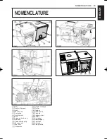
Page 23: ...e 6 Control panel 7 Base 8 Engine oil drain plug 9 Door lock 10 Coolant drain plug 11 Reserve tank 12 Fuel filter 13 Oil dipstick 14 Oil filter cartridge 15 Muffler 16 Radiator 17 Radiator cap 18 Solenoid 19 Engine oil port 20 Battery 21 Air cleaner 22 Door stopper 23 Fuel tank 24 Alternator 25 Safety shield ...

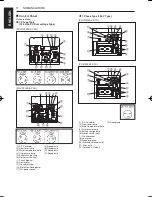
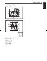
Page 24: ...tch key 7 Circuit breaker 8 Hour meter 9 Ground terminal 10 Protector Receptacle 11 Full power switch A Receptacle B Receptacle C Receptacle D Receptacle 1 Phase Type 220 V Type EDL11000SE STD 1 5 3 4 2 6 0 9 w 7 8 q A EDL7000SE STD 1 5 3 4 2 6 0 9 A w 7 8 q 1 A C Voltmeter 2 Glow timer lamp 3 Water temperature lamp 4 Oil pressure lamp 5 Battery charge lamp 6 Starter switch key 7 Circuit breaker 8...

Page 25: ...4 2 8 6 9 0 7 EDL7000SE AUS A 1 q 5 3 4 2 8 6 9 0 7 1 A C Voltmeter 2 Glow timer lamp 3 Water temperature lamp 4 Oil pressure lamp 5 Battery charge lamp 6 Starter switch key 7 Circuit breaker 8 Hour meter 9 Ground terminal 10 Protector Receptacle 11 Pilot lamp A Receptacles ...

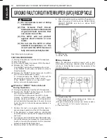
Page 26: ...firmly into the GFCI unit until an audible click is heard If the GFCI can not be reset the GFCI is faulty Contact a Yamaha dealer If the GFCI resets properly check such things as fault insulation or wet wiring inside the appliance or its cord If you ve found the short it should be repaired before it is used again 1 Perform this test on a regular monthly basis to ensure proper operation of the GFCI...

Page 27: ...RRUPTER GFCI RECEPTACLE Control Box EDL7000SE EDL7000SDE EDL11000SE EDL11000SDE 1 Emergency unit 2 Regulator 3 Glow relay 4 Relay A 5 Relay B 6 Glow lamp timer 7 Starter relay 8 Exterior connection terminal taps 9 Separate excitation unit ...

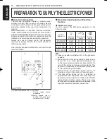
Page 28: ...pe system per N E C code Recommended Capacity of Electrical Devices Application range You can operate the EDL series generator in the following range Typical Apparatus Light and heaters Commutator motor Induction motor EDL7000SE 5 5 kW 2 8 kW 0 8 kW EDL7000SDE 6 5 kW 3 3 kW 0 8 kW EDL11000SE 8 kW 4 0 kW 1 2 kW EDL11000SDE 10 kW 5 0 kW 1 6 kW TIP 8 Keep an inverter load below 50 of the generator ca...

Page 29: ...oltage V Current A Power factor Power factors of commonly used devices are listed in the following table Load type Power factor Single phase induction motors 0 4 to 0 75 Electric heaters incandescent lamps 1 0 Commutator motor 0 8 to 0 95 Fluorescent lamps mercury lamps 0 4 to 0 9 AC arc welder 0 4 to 0 6 8 Ordinarily a motor is rated in kW This does not refer to motor output Motor input kVA Motor...

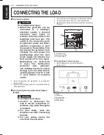
Page 30: ...r when normal operating power returns if unit is used without an isolation switch 1 Avoid connecting the generator to commercial power outlet 2 Avoid connecting the generator in parallel with any other generator Connecting the Load Terminal Output Model WARNING To avoid personal injury 8 Connect or disconnect the load to the AC receptacles or terminals only when the engine is stopped 8 For your sa...

Page 31: ...aker on the control panel C B A D 1 i 1 B C A B ii 1 Circuit breaker A Receptacle B Receptacle C Receptacle D Receptacle 2 Connect the load to the A C receptacles Connecting the Load AUS Model WARNING To avoid personal injury 8 Connect or disconnect the load to the AC receptacle only when the engine is stopped i EDL11000SE AUS 50 Hz 240 V ii EDL7000SE AUS 50 Hz 240 V 1 Turn OFF the circuit breaker...

Page 32: ...ator grounding Refuel See Fuel in PERIODIC SERVICE section Care of danger and warning labels See DANGER AND WARNING LABELS in SAFETY PRECAUTIONS section WARNING To avoid personal injury from contact with moving parts 8 DO NOT open the door or generator side cover while the engine is running 8 Do not touch muffler or exhaust pipes while they are hot Severe burns could result Battery The battery is ...

Page 33: ...ue to charge until all cells are gassing freely and the voltage and specific gravity reading in all cells remain constant for 3 or more successive readings taken at 30 minute intervals 8 When the battery has been charged fully the specific gravity of electrolyte should be 1 270 to 1 290 at 20 C 68 F Engine oil The generator has been shipped without engine oil Fill with oil to the correct level bef...

Page 34: ...garettes away from generator 1 Always fill the fuel through the fuel tank strainer 2 Make sure that dirt or water does not enter the fuel tank 3 Fill with Diesel fuel No 2 D ASTMD975 4 Below 0 C 32 F a mix of No 1 D and No 2 D is acceptable 5 Fuel level is read by fuel gauge TIP 8 If the fuel tank should empty completely causing the engine to stop then the fuel system requires air bleeding after f...

Page 35: ...1 Terminal cover is equipped with safety devices to detect the opening and or closing condition of cover 2 Safety switch 2 is located on the terminal cover If you turn the starter switch key to START with the terminal cover open the starter of engine will not activate 3 Turn the starter switch key to STOP to close the terminal cover and then restart the engine 4 If you open the terminal cover whil...

Page 36: ... section as to the preheating times 7 Turn the starter switch key to the START position and release when the engine starts 1 Starter switch key A OFF B ON C PREHEAT D START NOTICE 8 Do not run the starter motor continuously for more than 10 seconds at a time or it may damage the starter If the engine fails to start wait for about 30 seconds and try again 8 Check to see that the battery charge lamp...

Page 37: ... cold start it in the following manner Take steps 1 through 5 in Starting the Engine section 6 Turn the starter switch key to the PREHEAT position until the glow plug indicator goes off TIP 8 If the ambient temperature is low the preheating time will take longer NOTICE 8 Shown below are the standard preheating times for various temperatures This operation however is not required when the engine is...

Page 38: ... position take the following EMERGENCY STOP procedure WARNING To avoid personal injury 8 Keep your hands away from the rotating parts such as cooling fan and V belt Otherwise personal injury may be caused when manipulating the engine stop lever 1 Open the door using the door knob 2 Turn the engine stop lever to STOP direction and hold it for 5 to 10 seconds to shut off the engine 1 Engine stop lev...

Page 39: ...6 11 Cleaning of water jacket radiator interior 4 41 12 Replacement of fan belt 4 45 13 Check of valve clearance 4 14 Replacement of air cleaner element 4 38 2 15 Check of damage in electric wiring and loose connections 4 44 16 Check of fuel injection nozzle injection pressure 4 3 17 Check of injection pump 4 3 18 Replacement of fuel pipes fuel gauge and clamp bands 4 35 3 19 Replacement of radiat...

Page 40: ...n Petroleum Institute API service classification and Proper SAE Engine Oil according to the ambient temperatures as shown P37 8 With the emission control now in effect the CF 4 and CG 4 lubricating oils have been developed for use of a low sulfur fuel on on road vehicle engines When an off road vehicle engine runs on a high sulfur fuel it is advisable to employ the CF or better lubricating oil wit...

Page 41: ...nes in industrial and heavy mobile service SAE J313 JUN87 Grade of Diesel Fuel Oil According to ASTM D975 Flash Point C F Water and Sediment volume Carbon Residue on 10 percent Residuum Ash weight Min Max Max Max 52 125 0 05 0 35 0 01 Distillation Tempera tures C F 90 Point Viscosity Kinematic cSt or mm2 s at 40 C Viscosity Sayboit SUS at 100 F Sulfur weight Copper strip Corro sion Cetane Num ber ...

Page 42: ...bubbles do not come up any more 1 Fuel filter cock 2 Air vent plug 3 Fuel filter pot A OPEN B CLOSE Checking the fuel pipes WARNING To avoid personal injury 8 Check or replace the fuel pipes after stopping the engine Broken fuel pipes can cause fires Check the fuel pipes every 50 hours of operation When if 1 If the clamp band is loose apply oil to the screw of the band and tighten the band securel...

Page 43: ...h engine oil wash it off immediately TIP 8 Be sure to check the engine oil on a level surface If placed on gradients oil quantity can not be measured accurately NOTICE 8 Do not operate a diesel engine when engine oil is overfilled This can effect the air intake system which could result in engine damage or malfunction Checking oil level and adding engine oil 1 Check the engine oil level before sta...

Page 44: ...hen the engine is warm Inspect drain plug gasket Replace if damaged 1 Engine oil drain plug 3 Install the oil drain plug and gasket 4 Add new engine oil up to the upper line of the oil level gauge Replacing the oil filter cartridge WARNING To avoid personal injury 8 Be sure to stop the engine before changing the oil filter cartridge 8 Allow engine to cool down sufficiently Oil can be hot and cause...

Page 45: ...urally 6 After the element is fully dried inspect the inside of the element with a light and check if it is damaged or not referring to the instructions on the label attached to the element 7 Replace the primary element every year or every 6 cleanings If the primary element is heavily stained replace it sooner At this time also replace the secondary element 8 The secondary element should be remove...

Page 46: ...ounted air cleaner bodies the cup may be mounted in any direction Radiator Make it a rule to check the coolant level before every operation WARNING To avoid personal injury 8 DO NOT stop the engine suddenly stop it after about 5 minutes of unloaded idling 8 Work only after letting the engine and radiator cool off completely more than 30 minutes after it has been stopped 8 DO NOT remove the radiato...

Page 47: ...eak out and decrease the level quickly 8 When coolant is added coolant level may drop the first time the engine is started Stop the engine and add coolant if necessary Changing coolant 1 To drain coolant always remove both drain plugs and simultaneously open the radiator cap as well With the radiator cap kept closed the coolant will not drain completely Dispose of used coolant properly 2 Remove th...

Page 48: ...r outlet 3 Check to see if there is any dirt or dust between radiator fins and tube 4 Check to see if the fan belt is too loose and 5 Check to see if radiator water pipe is clogged Cleaning radiator core outside If dust is between the fin and tube wash it away with running water NOTICE 8 Do not clean radiator with firm tools such as spatulas or screwdrivers They may damage the delicate fins or tub...

Page 49: ...otection and rubber gloves since the diluted sulfuric acid solution burns skin and eyes and eats holes in clothing Should this occur immediately wash it off with running water and get medical attention Mishandling of the battery shortens the service life and adds to maintenance costs Obtain the maximum performance and the longest life of the battery by handling properly and with care Engine starti...

Page 50: ...14 to 15 1 Thick cable red 2 Battery case 3 Negative ground cable black 4 Plug A HIGHEST LEVEL B LOWEST LEVEL NOTICE 8 Connect the charger positive terminal to the battery positive terminal and negative to the negative 8 When disconnecting the cable from the battery start with the negative terminal first When connecting the cable to the battery start with the positive terminal first If reversed th...

Page 51: ...e 6 Clamp the other cable to the negative black or neg terminal of the helper battery 7 Clamp the other end to the engine block or frame of the generator as far from the dead battery as possible 8 Start the disabled generator 9 Disconnect the jumper cables in the exact reverse order of attachment Steps 7 6 and 5 10 Remove and discard the damp rags NOTICE 8 This machine has a 12 volt negative groun...

Page 52: ...ve the key before checking the belt tension 8 Be sure to reinstall the detached safety shield after maintenance or checking Proper fan belt tension A deflection of between 12 to 14 mm 0 47 to 0 55 in when the belt is pressed in the middle of the span 1 Stop the engine and remove the key 2 Apply moderate thumb pressure to belt between pulleys 3 If the belt tension is not as specified loosen the loc...

Page 53: ...g let the engine cool off Before storing the generator for more than a few months remove any dirt on the machine and 1 Remove dirty engine coolant fill with new coolant and run the engine for about 5 minutes When coolant is added coolant level drops the first time the engine is started stop the engine and add more coolant 2 Remove dirty engine oil fill with new oil and run the engine for about 5 m...

Page 54: ...ircuitry connected to output section Repair load Output cannot be obtained Rotation goes slow Voltage drops Breaker turns off Initial current is too much e g motor load Reduce load Overload Reduce load Engine indicates loaded condition Short circuit of generator wiring Stop immediately Request for repair Easy Checker Trouble Cause Countermeasure When the key is turned the lamp doesn t light on Bul...

Page 55: ...ed impurities or moisture Air and water are contained in the fuel supply line Check pipe and fastening clamp If any damage exists replace it or repair Relieve air Remove water inside of fuel tank and filter Injection pipe is loosened Re tighten Engine suddenly stops Fuel shortage Refuel Insufficient engine oil Fill oil Water temperature is too high Insufficient cooling water Loosened water pump be...

Page 56: ...exterior apparatus with the machine perform the following instructions 1 Remove the terminal taps cover 2 Connect the unit to the ectt with the wiring harnesses following the operator s manual of the A S S unit 3 To assemble the ttc set the ttc For nomenclature and connection of terminal taps are referred to the WIRING DIAGRAMS section See page 50 55 1 Plate 2 Exterior connection terminal taps ect...

Page 57: ...R METER STARTER SWITCH ATS TERMINAL AVR EXW SW RELAY FUSE BOX CONDENSER SLOW BLOW FUSE 40A 15A 10A 5A 3A REGULATOR BATTERY STARTER GLOW PLUG STOP SOLENOID OIL SWITCH GLOW RELAY STARTER RELAY GLOW LAMP TIMER WATER TEMPERATURE SWITCH RELAY DIODE 2 DIODE 1 C P 15A C P 15A R W R W LG Y W Y W Y W Y G O O Y Y Y L L L NC NO COM G G O O GR Y W Y R W R W B R B B W B Y Y B R Y W B R B B W R W R Y O R B Y W ...

Page 58: ...MBINATION LAMP HOUR METER STARTER SWITCH ATS TERMINAL AVR EXW SW RELAY FUSE BOX CONDENSER SLOW BLOW FUSE 40A 15A 10A 5A 3A REGULATOR BATTERY STARTER GLOW PLUG STOP SOLENOID OIL SWITCH GLOW RELAY STARTER RELAY GLOW LAMP TIMER WATER TEMPERATURE SWITCH RELAY DIODE 2 DIODE 1 250V 15A 250V 15A C P 15A C P 15A R W R W LG Y Y W Y G O O Y O O GR Y W Y R W R W B R B B W B Y Y B R Y W B R B B W R W R Y O R ...

Page 59: ...R STARTER SWITCH ATS TERMINAL AVR EXW SW 1 RELAY FUSE BOX SLOW BLOW FUSE 40A 15A 10A 5A 3A REGULATOR BATTERY STARTER GLOW PLUG STOP SOLENOID OIL SWITCH GLOW RELAY STARTER RELAY GLOW LAMP TIMER WATER TEMPERATURE SWITCH RELAY DIODE 2 DIODE 1 120 240V 120V 1 2 3 4 5 7 8 6 2 NFB BR 18 BR 18 W 18 G 10 G 10 G 10 G 10 G 10 LG Y Y W Y G O O Y O O GR Y W Y R W R W B R B B W B Y Y B R Y W B R B B W BR 18 BR...

Page 60: ...UNIT SLOW BLOW FUSE 50A 15A 10A 8A 1A 5A 5A 3A REGULATOR BATTERY STARTER GLOW PLUG STOP SOLENOID OIL SWITCH GLOW RELAY STARTER RELAY GLOW LAMP TIMER WATER TEMPERATURE SWITCH RELAY DIODE 2 DIODE 1 C P 15A C P 15A R W R W LG Y W Y W Y W Y G O O Y Y Y L L L NC NO COM G G O O GR Y W Y R W R W B R B B W B Y Y B R Y W B R B B W R W R Y O R B Y W R W B Y Y B G Y Y G G O L W L W EMERGENCY UNIT EG 1 SEPARA...

Page 61: ...RTER SWITCH ATS TERMINAL AVR EXW SW RELAY FUSE BOX CONDENSER DIODE UNIT SLOW BLOW FUSE 50A 15A 10A 5A 5A 8A 1A 3A REGULATOR BATTERY STARTER GLOW PLUG STOP SOLENOID OIL SWITCH GLOW RELAY STARTER RELAY GLOW LAMP TIMER WATER TEMPERATURE SWITCH RELAY DIODE 2 DIODE 1 250V 15A 250V 15A 250V 15A C P 15A C P 15A C P 15A R W R W R W LG Y Y W Y G O O Y O O GR Y W Y R W R W B R B B W B Y Y B R Y W B R B B W ...

Page 62: ...GLOW PLUG STOP SOLENOID OIL SWITCH GLOW RELAY STARTER RELAY GLOW LAMP TIMER WATER TEMPERATURE SWITCH RELAY DIODE 2 DIODE 1 4 5 NFB BR 18 G 8 G 8 G 8 G 8 G 8 G 5mm 2 G 8 L 8 L 8 L 8 L 8 W 8 G 10 L 10 G 8 G 10 G 12 G 12 W 10 R 10 L 12 L 12 LG Y Y W Y G O O Y O O GR Y W Y R W R W B R B B W B Y Y B R Y W B R B B W BR 18 BR 18 R Y O R B Y W B Y Y B G Y Y G G O 18 W EMERGENCY UNIT EG 1 1 2 3 4 5 6 7 14 ...

Reviews: