27
DXR8/DXR10/DXR12/DXR15
PIN
NO.
I/O
FUNCTION
NAME
PIN
NO.
I/O
FUNCTION
NAME
1
2
3
4
5
6
7
8
9
10
11
12
13
14
15
16
17
18
19
20
21
22
23
24
25
26
27
28
29
30
31
32
I2C1_SCL
I2C1_SDA
GPIO2
GPIO1
MUTE
CS0
PDN
DVSS1
DVDD1
VR_PLL
AVSSI
AIN1LP
AIN1LM
AIN1RP
AIN1RM
AIN2LP
AIN2LM
AIN2RP
AIN2RM
AIN3LP
AIN3LM
AIN3RP
AIN3RM
AVDD1
VMID
VREF
REXT
AVDD2
AOUT2LM
AOUT2LP
AOUT2RM
AOUT2RP
I
I/O
I/O
I/O
I
I
I
-
-
-
-
I
I
I
I
I
I
I
I
I
I
I
I
-
O
O
O
-
O
O
O
O
Slave I
2
C serial clock input
Slave I
2
C serial control data interface input/output
General purpose input/output #2
General purpose input/output #1
This pin needs to be programmed as mute
pin in the application code.
I
2
C chip select
Powerdown active LOW
Digital ground
Digital power 3.3 V
Voltage reference for DPLL supply
Analog ground
Analog channel 1 left positive input
Analog channel 1 left negative input
Analog channel 1 right positive input
Analog channel 1 right negative input
Analog channel 2 left positive input
Analog channel 2 left negative input
Analog channel 2 right positive input
Analog channel 2 right negative input
Analog channel 3 left positive input
Analog channel 3 left negative input
Analog channel 3 right positive input
Analog channel 3 right negative input
Analog power 3.3 V
Analog mid supply reference
Band gap output
This pin must be connected to a 22 k
Ω
(1% tolerance)
external resistor to ground to set analog currents.
Analog power 3.3 V
Analog channel 2 left negative output
Analog channel 2 left positive output
Analog channel 2 right negative output
Analog channel 2 right positive output
33
34
35
36
37
38
39
40
41
42
43
44
45
46
47
48
49
50
51
52
53
54
55
56
57
58
59
60
61
62
63
64
AOUT1LM
AOUT1LP
AOUT1RM
AOUT1RP
AVSSO
AVSS_ESD
VR_ANA
AVDD3
XTAL_IN
XTAL_OUT
MCLK_IN
DVSS2
DVDD2
MCLK_OUT3
MCLK_OUT2
MCLK_OUT1
VREG_EN
RESERVED
LRCLK_OUT
SCLK_OUT
SDO2
SDO1
VR_DIG
DVSS3
DVDD3
LRCLK_IN
SCLK_IN
SDIN2/GPIO4
SDIN1/GPIO3
RESET
I2C2_SDA
I2C2_SCL
O
O
O
O
-
-
-
-
I
O
I
-
-
O
O
O
I
-
O
O
O
O
-
-
-
I
I
I/O
I/O
I
I/O
I
Analog channel 1 left negative output
Analog channel 1 left positive output
Analog channel 1 right negative output
Analog channel 1 right positive output
Analog ground
Voltage reference for analog supply
Analog power 3.3 V
Crystal input
Crystal output
Master clock input for I
2
S interface
Digital ground
Digital power 3.3 V
Programmable master clock output divider
Master clock output for I
2
S interface
Voltage regulator enable active low
Pin must be connected to ground
Left/right (frame) clock output for I
2
S interface
Serial (bit) clock output for I
2
S interface
Serial data output #2 for I
2
S interface
Serial data output #1 for I
2
S interface
Voltage reference for digital supply
Digital ground
Digital power 3.3 V
Left/right (frame) clock input for I
2
S interface
Serial (bit) clock input for I
2
S interface
Serial data input #2 for I
2
S interface /
General purpose input/output #4
Serial data input #1 for I
2
S interface /
General purpose input/output #3
Device reset
Master I
2
C serial control data interface input/output
Master I
2
C serial clock input
TAS3204PAGR
(YA768A00)
DSP
(Digital Signal Processor)
DSP: IC702
AMPS Circuit Board
(YC775F00) ........................................................ 28/29
DSP Circuit Board
(YD229D0) ............................................................ 30/31
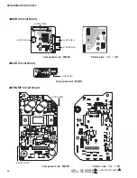
LED Circuit Board
(YD441C0) .................................................................. 34
SUB1 Circuit Board
(YD233D0) ............................................................... 32
SUB2 Circuit Board
(YD233D0) ............................................................... 33
SUB3 Circuit Board
(YD233D0) ............................................................... 33
SUB4 Circuit Board
(YD233D0) ............................................................... 34
TWAMP Circuit Board
(YD206E0) ............................................................ 34
CIRCUIT BOARDS
(シート基板図)
Note: See parts list for details of circuit board component parts.
注 :
シートの部品詳細は、パーツリストをご参照ください。
Summary of Contents for DXR Series
Page 29: ...29 DXR8 DXR10 DXR12 DXR15 Pattern side パターン側 AMPS Circuit Board Scale 90 100 2NA WW65240 2 ...
Page 31: ...31 DXR8 DXR10 DXR12 DXR15 2NA WW59820 3 Pattern side パターン側 DSP Circuit Board to AMPS CN255 ...
Page 73: ... G O HWDLOV A 部詳細 SDUWV RI 100 の部品 7 03 66 0 TWAMP Ass y 6HH SDJH 13 DXR8 DXR10 DXR12 DXR15 ...


