17
DXR8/DXR10/DXR12/DXR15
B-4. Speaker
(Tweeter)
(Time required: About 5 minutes)
B-4-1 Remove the metal grille assembly. (See procedure B-1.)
B-4-2 Remove the baf
fl
e assembly. (See procedure B-3.)
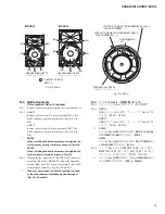
B-4-3 Remove the HFSPOUT connector assembly (yellow/
blue) attached to the speaker (tweeter) terminal.
(Fig. B-7, Fig. B-8)
B-4-4 Remove the four (4) screws marked [90]. The TW plate
can then be removed together with the speaker (tweeter).
(Fig. B-7, Fig. B-8)
*
When installing the TW plate, fi rst tighten the two (2)
priority screws as shown in Fig. B-8.
B-4-5 Remove the four (4) screws marked [80] and four
(4) toothed lock washers marked [280]. The speaker
(tweeter) can then be removed from the TW plate.
(Fig.
B-7)
B-5. LED Circuit Board
(Time required: About 4 minutes)
B-5-1 Remove the metal grille assembly. (See procedure B-1.)
B-5-2 Remove the baf
fl
e assembly. (See procedure B-3.)
B-5-3 Remove the two (2) screws marked [170]. The LED
circuit board can then be removed. (Fig. B-8, Fig. B-9)
B-6. Amp
Assembly
(Time required: About 6 minutes)
B-6-1 Remove the metal grille assembly. (See procedure B-1.)
B-6-2 Remove the speaker (woofer). (See procedure B-2.)
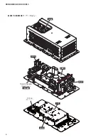
B-6-3 Disconnect the connectors of the LFSPOUT connector
assembly (red/black), HFSPOUT connector assembly
(yellow/blue) and C&C connector assembly (red/white)
from the amp assembly. (Fig. B-10, Photo B-2)
B-6-4 Remove the twelve (12) screws marked [130].
(Fig.
B-10)
*
When installing the amp assembly, fi rst tighten the
priority screw as shown in Fig. B-10.
B-6-5 Loosen the two (2) screws for removing the amp
assembly. (Fig. B-11)
*
Loosen only ! Never remove these screws. Tighten
these screws when installing the amp assembly.
(Fig.
B-11)
B-6-6 Hold the two (2) screws for removing the amp
assembly and then remove the amp assembly carefully.
(Fig. B-11)
For about disassembly of amp assembly, refer to 20
page.
B-4. スピーカ(ツイーター)
(所要時間:約 5 分)
B-4-1 メタルグリル Ass'y を外します。(B-1 項参照)
B-4-2 バッフル Ass'y を外します。(B-3 項参照)
B-4-3 スピーカ(ツイーター)端子に取り付けられてい
る HFSPOUT 束線(黄/青)を外します。
(図 B-7、図 B-8)
B-4-4 [90] のネジ 4 本を外して、スピーカ(ツイーター)
と共に TW プレートを外します。(図 B-7、図 B-8)
※
TW プレートを取り付けるときは、図に示す優先ネジ 2
本を先に締めてください。(図 B-8)
B-4-5 [80] のネジ 4 本と [280] の歯付座金外歯 4 個を外
して、TW プレートからスピーカ(ツイーター)
を外します。(図 B-7)
B-5. LED シート
(所要時間:約 4 分)
B-5-1 メタルグリル Ass'y を外します。(B-1 項参照)
B-5-2 バッフル Ass'y を外します。(B-3 項参照)
B-5-3 [170] のネジ 2 本を外して、LED シートを外します。
(図 B-8、図 B-9)
B-6. アンプ Ass'y
(所要時間:約 6 分)
B-6-1 メタルグリル Ass'y を外します。(B-1 項参照)
B-6-2 スピーカ(ウーファー)を外します。(B-2 項参照)
B-6-3 ア ン プ Ass'y か ら LFSPOUT 束 線( 赤 / 黒 )、
HFSPOUT 束線(黄/青)、C&C 束線(赤/白)
のコネクターを外します。(図 B-10、写真 B-2)
B-6-4 [130] のネジ 12 本を外します。(図 B-10)
※
アンプ Ass'y を取り付けるときは、図に示す優先ネジ 1
本を先に締めてください。(図 B-10)
B-6-5 アンプ Ass'y 取り外し用ネジ 2 本を緩めます。
(図 B-11)
※
これらのネジは緩めるだけで、外さないように注意して
ください。アンプ Ass'y 取り付け時には、これらのネジ
を締めてください。(図 B-11)
B-6-6 アンプ Ass'y 取り外し用ネジ 2 箇所を持って、慎
重にアンプ Ass'y を外します。(図 B-11)
アンプ Ass'y の分解手順は、20 ページを参照して
ください。
Summary of Contents for DXR Series
Page 29: ...29 DXR8 DXR10 DXR12 DXR15 Pattern side パターン側 AMPS Circuit Board Scale 90 100 2NA WW65240 2 ...
Page 31: ...31 DXR8 DXR10 DXR12 DXR15 2NA WW59820 3 Pattern side パターン側 DSP Circuit Board to AMPS CN255 ...
Page 73: ... G O HWDLOV A 部詳細 SDUWV RI 100 の部品 7 03 66 0 TWAMP Ass y 6HH SDJH 13 DXR8 DXR10 DXR12 DXR15 ...


