background image

19

DTXPRESS 

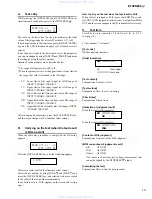
A.

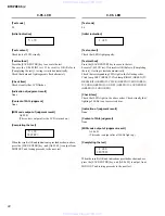
Test entry

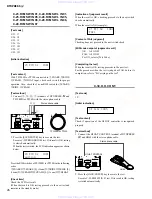
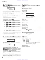
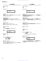
While pressing the [DRUM KIT] and [SAVE/ENTER] keys
simultaneously, turn on the power to the DTXPRESS 

.

DIAG


att


cr


xt


677f


2450


04

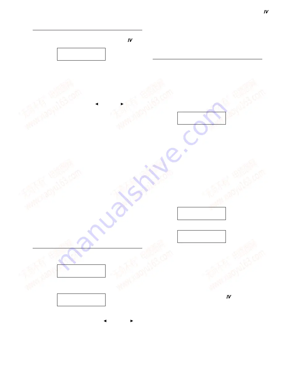
The value on the lower level on the screen indicates the limit
value of the trigger input level test of Test items C-11 to 22.
If no change is made to the limit value, press the [SAVE/ENTER]
key, and the LCD indication changes to [Test number select
screen].
If any change is made to the limit value, select the parameter
you want to change by using [PAGE  ] and [PAGE  ] and make
the setting by using the rotary encoder.
Details of each parameter are as described below.

* The range of all parameters is 00 to ff.
* When the parameter is set at the upper limit or lower limit in

the range, that value is included in the OK range.

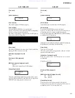
67

:

Lower limit of the input signal level OK range of
INPUT 

q

SNARE–

i

KICK/9

7f

:

Upper limit of the input signal level OK range of
INPUT 

q

SNARE–

i

KICK/9

24

:

Lower limit of the time constant value OK range of
INPUT 

q

SNARE–

i

KICK/9

50

:

Upper limit of the time constant value OK range of
INPUT 

q

SNARE–

i

KICK/9

04

:

Upper limit of the crosstalk value OK range of INPUT

q

SNARE–

i

KICK/9

After changing all parameters, press the [SAVE/ENTER] key,
and the screen changes to [Test number select screen].

B.

Carrying on the test (when the test result
is FAIL as well)

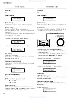
When the test entry procedure is completed, the following
appears.

DIAG


att


cr


xt


677f


2450


04

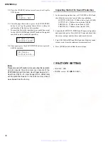
Press the [SAVE/ENTER] key, and the following appears.


1


ROM

This screen state is called [Test number select screen].
Select the test number by using [PAGE  ] and [PAGE  ] and
press the [SAVE/ENTER] key, and selected tests are executed
in the order of the test number automatically,
If any failure occurs, FAIL appears on the screen and testing
stops.

How to carry on the test when the test result is FAIL

When the test is judged as FAIL, press the [SHIFT] key, and
[A0 XX 03] (XX represents each test code) is output from MIDI
OUT and the screen changes to the [Test number select screen].

C.

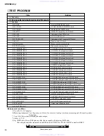
Test item

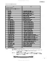
Listed below are contents of tests from C-01 to C-35.
(See page 18)

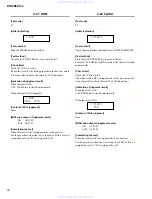
C-"test number", "test name"

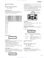
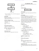
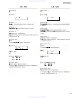
[Test code]

XX (hexadecimal number)

[Initial indication]

XX ○○○○○○

XX:

Test number

○○○○○○: Test name

[Test content]

Explanation of contents of test

[Test method]

Explanation of how to carry on testing

[Check item]

Explanation of check items

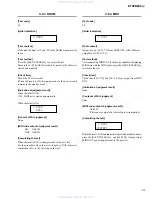
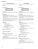
[Indication of judgment result]

When the result is OK (example)

XX ○○○○○○

OK

When the result is NG (example)

XX ○○○○○○

FAIL

[Content of FAIL judgment]

Explanation of contents of the FAIL judgment

[MIDI code output of judgment result]

OK

A0 XX 02

FAIL

A0 XX 03

Others

A0 XX 01

(Test items such as visual test, voltage measurement, that
cannot be judged by the DTXPRESS 

 alone)

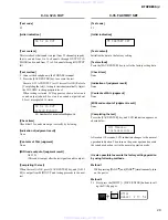
[Completing the test]

Explanation of how to end the test procedure

www. xiaoyu163. com

QQ 376315150

9

9

2

8

9

4

2

9

8

TEL 13942296513

9

9

2

8

9

4

2

9

8

0

5

1

5

1

3

6

7

3

Q

Q

TEL  13942296513  QQ  376315150  892498299 

TEL  13942296513  QQ  376315150  892498299 

http://www.xiaoyu163.com

http://www.xiaoyu163.com

Summary of Contents for DTXPRESS IV

Page 1: ...基板図 14 TEST PROGRAM テストプログラム 18 31 FACTORY SETTING 出荷時の設定 30 43 ERROR MESSAGES エラーメッセージ 44 SYSTEM BOOTING FLOWCHART 起動フローチャート 45 46 MIDI IMPLEMENTATION CHART 47 MIDI DATA FORMAT 48 PARTS LIST BLOCK DIAGRAM ブロックダイアグラム OVERALL CIRCUIT DIAGRAM 総回路図 20061215 オープンプライス HAMAMATSU JAPAN DRUM TRIGGER MODULE www xiaoyu163 com QQ376315150 9 9 2 8 9 4 2 9 8 TEL 13942296513 9 9 2 8 9 4 2 9 8 0 5 1 5 1 3 6 7 3 ...

Page 2: ...NT Turn the unit OFF during disassembly and parts replacement Recheck all work before you apply power to the unit WARNING CHEMICAL CONTENT NOTICE The solder used in the production of this product contains LEAD In addition other electrical electronic and or plastic where applicable components may also contain traces of chemicals found by the California Health and Welfare Agency and possibly other e...

Page 3: ...30 Click Timer 0 600 seconds in 30 second steps Training Functions Measure Break Groove Check Rhythm Gate Others Controls Buttons DRUMKIT CLICK SONG SHIFT ON OFF SAVE ENTER Controllers Volume Jog Dial Displays 16 characters x 2 lines backlit LCD 7 segment LED 3 digit Tempo LED x 2 Connectors Trigger inputs 1 5 6 7 stereo phone jack L trigger input R rim switch Trigger inputs 2 3 4 8 stereo phone j...

Page 4: ... クリックセット 30種類 クリックタイマー 0 600秒 30秒間隔 練習機能 メジャーブレイク グルーブチェック リズムゲート その他 操作子 ボタン DRUMKIT CLICK SONG SHIFT ON OFF SAVE ENTER コントローラー ボリューム ジョグダイアル ディスプレイ 16文字 2行 バックライト付LCD 3桁 7セグメントLED テンポ確認用LED 2 接続端子 トリガー入力 1 5 6 7 ステレオ標準フォーン端子 L トリガー R リムスイッチ トリガー入力 2 3 4 8 ステレオ標準フォーン端子 L トリガー R トリガー HI HAT CONTROL ステレオ標準フォーン端子 OUTPUT L MONO R 標準フォーン端子 PHONES ステレオ標準フォーン端子 AUX IN ステレオミニ端子 MIDI OUT DC IN 消費電力 13 0W ...

Page 5: ...display 0 LCD display 1 Jog dial q ドラムキットボタン DRUM KIT w クリックボタン CLICK e ソングボタン SONG r シフトボタン SHIFT t セレクトボタン y クリック ON OFF ボタン ON OFF u セーブ エンターボタン SAVE ENTER i クリックランプ o LED ディスプレイ 0 LCD ディスプレイ 画面 1 ジョグダイアル www xiaoyu163 com QQ376315150 9 9 2 8 9 4 2 9 8 TEL 13942296513 9 9 2 8 9 4 2 9 8 0 5 1 5 1 3 6 7 3 Q Q TEL 13942296513 QQ 376315150 892498299 TEL 13942296513 QQ 376315150 892498299 http www x...
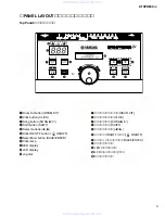
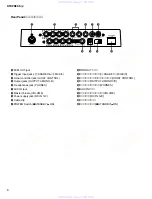
Page 6: ...Cable clip 1 POWER Switch STANDBY ON 2 MIDI OUT 端子 3 トリガー入力端子 qSNARE iKICK 9 4 ハイハットコントロール端子 HI HAT CONTROL 5 出力端子 OUTPUT L MONO R 6 ヘッドフォン端子 PHONES 7 AUX IN 端子 8 マスターボリューム VOLUME 9 電源端子 DC IN 12V 0 コードフック 1 電源スイッチ STANDBY ON www xiaoyu163 com QQ376315150 9 9 2 8 9 4 2 9 8 TEL 13942296513 9 9 2 8 9 4 2 9 8 0 5 1 5 1 3 6 7 3 Q Q TEL 13942296513 QQ 376315150 892498299 TEL 13942296513 QQ 376315150 89...

Page 7: ...ダードセット DTXPRESS Special Set スペシャルセット www xiaoyu163 com QQ376315150 9 9 2 8 9 4 2 9 8 TEL 13942296513 9 9 2 8 9 4 2 9 8 0 5 1 5 1 3 6 7 3 Q Q TEL 13942296513 QQ 376315150 892498299 TEL 13942296513 QQ 376315150 892498299 http www xiaoyu163 com http www xiaoyu163 com ...
Page 8: ...PN CN305 to PN CN304 to PN CN303 to PN CN306 Inside View 1 内部図1 Inside View 2 内部図2 Component side 部品側 Pattern side パターン側 Pattern side パターン側 www xiaoyu163 com QQ376315150 9 9 2 8 9 4 2 9 8 TEL 13942296513 9 9 2 8 9 4 2 9 8 0 5 1 5 1 3 6 7 3 Q Q TEL 13942296513 QQ 376315150 892498299 TEL 13942296513 QQ 376315150 892498299 http www xiaoyu163 com http www xiaoyu163 com ...
Page 9: ...oved Fig 2 2 ボトムケース 所要時間 約2分 2 1 フロントケースを外します 1項参照 2 2 160B のネジ4本を外します 図1 2 3 160C のネジ3本を外して ボトムケースを外しま す 図2 160A 160B Front case フロン トケース Bottom case ボ トムケース Cord column コー ド コラム 160C 160C 160C 160D 160E 160E Encoder knob エンコーダツマ ミ 160A 160B Bind Head Tapping Screw B Bタイト BIND 3 0X12 MFZN2B3 WE998100 Fig 1 図1 注意事項 フラットケーブルの表 裏を逆に差し込まないように 注意して取り付けてください 図A Caution Pay attention not to insert and i...

Page 10: ...ee procedure 3 4 4 Remove the encoder knob Fig 2 4 5 Remove the two 2 screws marked 160E Fig 2 4 6 Remove the eight 8 screws marked 180 and the two 2 flat washers marked 190 The PN circuit board can then be removed Fig 4 When mounting the PN circuit board always start by tightening screws with washers q w in sequence Fig 4 4 PNシート 所要時間 約5分 4 1 フロントケースを外します 1項参照 4 2 ボトムケースを外します 2項参照 4 3 DMシートを外します ...

Page 11: ...126 PDT14 I O SWX access data bus 43 SRAS O RAS signal 127 PDT13 I O SWX access data bus 44 SCAS O CAS signal 128 PDT12 I O SWX access data bus 45 REFRESH O REFRESH signal 129 PDT11 I O SWX access data bus 46 CS0 O CS signal 130 PDT10 I O SWX access data bus 47 SMA0 O Memory address bus 131 PDT9 I O SWX access data bus 48 SMA16 O Memory address bus 132 PDT8 I O SWX access data bus 49 VCC49 Power s...

Page 12: ... H H L H Q O H L H H L Q O X X X H L X X X X f f L H L L H H H L H L H H H 1 2 3 4 5 6 7 1CLR 1D 1CK 1PR 1Q 1Q GND 14 13 12 11 10 9 8 VCC 2CLR CLR 2D D 2CK CK 2PR PR 2Q 2Q Q Q CLR D CK PR Q Q SN74LV245APWR X3693A00 Octal 3 State Bus Transceiver DM IC21 1 2 3 4 5 6 7 20 19 18 17 16 15 14 Vcc G B1 B2 B3 B4 B5 B6 B7 B8 8 9 10 12 11 GND A8 A7 A6 A5 A4 A3 A2 A1 D1R 13 SN74LV374APWR X3225A00 Octal 3 Sta...

Page 13: ...M IC29 1 2 3 5 4 NC GND Vcc OUT Y IN A SN74AHC1G08DCKR X3833A00 Single 2 Input Positive AND Gate DM IC30 32 1 2 3 A B GND 5 4 Vcc Y INPUTS FUNCTION TABLE OUTPUT A B Y H L L H X L H L X NJM2902M TE1 X4983A00 Quad Operational Amplifier DM IC22 24 PN IC301 306 308 1 2 3 4 5 6 7 Output A Inverting Input A Non inverting Input A DC Voltage Supply Non inverting Input B Inverting Input B Output B 14 13 12...

Page 14: ... シート基板図 Note See parts list for details of circuit board component parts 注 シートの部品詳細は パーツリストをご参照ください www xiaoyu163 com QQ376315150 9 9 2 8 9 4 2 9 8 TEL 13942296513 9 9 2 8 9 4 2 9 8 0 5 1 5 1 3 6 7 3 Q Q TEL 13942296513 QQ 376315150 892498299 TEL 13942296513 QQ 376315150 892498299 http www xiaoyu163 com http www xiaoyu163 com ...
Page 15: ...ン側 2NA WH02300 2 1 www xiaoyu163 com QQ376315150 9 9 2 8 9 4 2 9 8 TEL 13942296513 9 9 2 8 9 4 2 9 8 0 5 1 5 1 3 6 7 3 Q Q TEL 13942296513 QQ 376315150 892498299 TEL 13942296513 QQ 376315150 892498299 http www xiaoyu163 com http www xiaoyu163 com ...
Page 16: ... ENTER LD308 7 PWB 0 0 5 mm Component side 部品側 2NA WH02300 1 3 PN Circuit Board www xiaoyu163 com QQ376315150 9 9 2 8 9 4 2 9 8 TEL 13942296513 9 9 2 8 9 4 2 9 8 0 5 1 5 1 3 6 7 3 Q Q TEL 13942296513 QQ 376315150 892498299 TEL 13942296513 QQ 376315150 892498299 http www xiaoyu163 com http www xiaoyu163 com ...
Page 17: ...1 PN Circuit Board www xiaoyu163 com QQ376315150 9 9 2 8 9 4 2 9 8 TEL 13942296513 9 9 2 8 9 4 2 9 8 0 5 1 5 1 3 6 7 3 Q Q TEL 13942296513 QQ 376315150 892498299 TEL 13942296513 QQ 376315150 892498299 http www xiaoyu163 com http www xiaoyu163 com ...
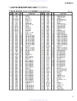
Page 18: ...IN 01 q SNARE Rch pad switch ON OFF check C 24 RIM SW L IN 01 q SNARE Rch pad switch ON OFF check 3zone C 25 RIM SW IN 05 t RIDE Rch pad switch ON OFF check C 26 RIM SW L IN 05 t RIDE Rch pad switch ON OFF check 3zone C 27 RIM SW IN 06 y CRASH Rch pad switch ON OFF check C 28 RIM SW L IN 06 y CRASH Rch pad switch ON OFF check 3zone C 29 RIM SW IN 07 u HI HAT Rch pad switch ON OFF check C 30 H H CO...

Page 19: ... appears DIAG att cr xt 677f 2450 04 Press the SAVE ENTER key and the following appears 1 ROM This screen state is called Test number select screen Select the test number by using PAGE and PAGE and press the SAVE ENTER key and selected tests are executed in the order of the test number automatically If any failure occurs FAIL appears on the screen and testing stops How to carry on the test when th...

Page 20: ...st content Check the manufacture code and device ID of FLASH ROM Test method Press the SAVE ENTER key to execute the test Execute C 01 ROM test and if its result is OK the test is started automatically Check item Check the LCD test result When the result is OK testing proceeds to the next test and so it is not possible to check the result by LCD indication Indication of judgment result When the re...

Page 21: ...fer to B Carrying on the test C 04 MIDI Test code 04 Initial indication 4 MIDI Test content Output key on 90 3C 7F from MIDI OUT After 500msec output key off 90 3C 00 Test method After connecting MIDI OUT to the device capable of displaying MIDI data with the MIDI cable press the SAVE ENTER key to execute the test Check item Check that 90 3C 7F and 90 3C 00 are output from MIDI OUT Indication of j...

Page 22: ...ss the SAVE ENTER key to execute the test Execute C 05 LCD test If its result is OK Refer to Completing the test testing is started automatically Check that corresponding LEDs light in the following order Click lamp LEFT RED Click lamp RIGHT GREEN DRUM KIT GREEN CLICK GREEN SONG RED SONG GREEN ON OFF GREEN SAVE ENTER GREEN SONG RED Check item Check that LEDs light in the above order Check visually...

Page 23: ... that he panel switches turns ON OFF properly Test method Press the SAVE ENTER key to execute the test Execute C 07 7SEG LED test If its result is OK Refer to Completing the test testing is started automatically Turn on panel switches from DRUM KIT to SAVE ENTER according to the LCD indication 8 SW KIT DRUM KIT CLICK SONG SHIFT PAGE PAGE ON OFF SAVE ENTER Check item Check the LCD test result When ...

Page 24: ...fer to B Carrying on the test C 10 PAD Encoder Test code 0A Initial indication 10 PAD Encoder Test content Check that operation of the pad encoder is recognized properly Test method 1 Connect qSNARE terminal of DTXPRESS and TP120SD or TP100 with the stereo phone cable 2 Press the SAVE ENTER key to execute the test Execute C 09 R Encoder test If its result is OK testing is started automatically Tur...

Page 25: ... to MAX Input the signal output from PHONES in the following order qSNARE Lch wTOM1 10 Lch wTOM1 10 Rch eTOM2 11 Lch eTOM2 11 Rch rTOM3 12 Lch r TOM3 12 Rch t RIDE Lch y CRASH Lch uHI HAT Lch iKICK 9 Lch iKICK 9 Rch q t y and u operate by the monaural phone cable but the stereo phone cable is also usable for checking them Check item Check the LCD test result When the result is OK testing proceeds ...

Page 26: ... standby mode Indication of judgment result When the result is OK checking proceeds to the next switch check automatically When the result is NG example 23 RIM SW IN01 FAIL Content of FAIL judgment Checking does not proceed to the next switch check MIDI code output of judgment result OK A0 XX 02 FAIL A0 XX 03 For XX refer to Test Code Completing the test When the result is OK testing proceeds to t...

Page 27: ...to both of OUTPUT L MONO and R and measure frequency waveform level and total harmonic distortion of each output signal After that disconnect the plug connected to OUTPUT R and measure the output of OUTPUT L MONO again Check to make sure that the plug is not connected to AUX IN Check item OUTPUT L MONO Frequency 1kHz 3Hz Waveform Sine wave Level 5 5 2dBu load of 10kΩ Total Harmonic Distortion 0 5 ...

Page 28: ...utput signal which is inputted from AUX IN is correct Test method Press the SAVE ENTER key to execute the test Execute C 32 OUTPUT R 1kHz test If its result is OK Refer to Completing the test testing is started automatically Set VOLUME to MAX Input the sine wave to AUX IN Lch and Rch connect the standard stereo phone plug to PHONES and measure the output waveform level and total harmonic distortio...

Page 29: ... OK press SAVE ENTER key and A0 22 02 is output from MIDI OUT and testing proceeds to the next test C 35 FACTORY SET Test code 23 Initial indication 35 FACTORY SET Test content Initialize the data to the factory setting Test method Press the SAVE ENTER key to set to the factory setting data Check item None Indication of judgment result None Contents of FAIL judgment None MIDI code output of judgme...

Page 30: ...TTING VOLUME MIN POWER switch OFF STANDBY UTIL8 π Factory Set All data will be lost AreYouSure All Memory Initializing Inspecting the Unit for Sound Production 1 In the normal operation state set VOLUME to MAX and check that the noise level meets following conditions OUTPUT L MONO 75dBu or lower load of 10kΩ OUTPUT R 75dBu or lower load of 10kΩ PHONES L 75dBu or lower load of 33Ω PHONES R 75dBu or...

Page 31: ...el check C 22 TRIGGER IN 09 i KICK 9 Rch input level check C 23 RIM SW IN 01 q SNARE Rch pad switch ON OFF check C 24 RIM SW L IN 01 q SNARE Rch pad switch ON OFF check 3zone C 25 RIM SW IN 05 t RIDE Rch pad switch ON OFF check C 26 RIM SW L IN 05 t RIDE Rch pad switch ON OFF check 3zone C 27 RIM SW IN 06 y CRASH Rch pad switch ON OFF check C 28 RIM SW L IN 06 y CRASH Rch pad switch ON OFF check 3...

Page 32: ...450 04 SAVE ENTER を押すと 以下の画面が表示されます 1 ROM この状態を テストナンバー選択画面 とします PAGE 及び PAGE を用いてテストナンバーを選択し SAVE ENTER を押すと 選択されたテストからテストナン バー順に自動的にテストが実行されます 不良が発生した場合 FAIL表示を行なってテストは止まりま す FAILと判断した時のテストの進め方 各テストにおいてFAILと判断した場合 SHIFT を押すと MIDI OUTから A0 XX 03 XXは各テストコード が出力され テストナンバー選択画面 に戻ります C テスト項目 C 01 C 35までのテスト内容を 下記に示します 31ページ 参照 C テストナンバー テスト名 テストコード XX HEX表示 最初の表示 XX XX テストナンバー テスト名 テスト内容 テスト内容の説明 テスト...

Page 33: ...FLASH テスト内容 FLASH ROMのマニュファクチュアコード デバイスIDを確 認します テスト方法 SAVE ENTER を押して テストを実行させます C 01 ROMテストを行ないOKの場合は 自動的にスタートし ます チェック項目 LCDのテスト結果を確認します OKの場合は 自動的に次のテストを実行しますので表示の 確認はできません 判定結果の表示 OKの時 自動的にC 03 SRAMテストを開始する NGの時 2 FLASH FAIL FAIL判定内容 なし 判定結果のMIDIコード出力 OK A0 02 02 FAIL A0 02 03 テストの終了方法 OKの時は 次のテストに進みます テスト途中でFAILと判定された場合の処理方法は B テスト の進め方 を参照してください www xiaoyu163 com QQ376315150 9 9 2 8 9 4 2 9...

Page 34: ...コード 04 最初の表示 4 MIDI テスト内容 MIDI OUTからkey on 90 3C 7F を出力します 500msec後 key off 90 3C 00 を出力します テスト方法 MIDI OUTとMIDIデータを表示できる機器をMIDIケーブル で接続したあと SAVE ENTER を押して テストを実行し ます チェック項目 MIDI OUTから 90 3C 7F 90 3C 00 が送られていること を確認します 判定結果の表示 なし FAIL判定内容 なし 判定結果のMIDIコード出力 A0 04 01 テストデータ送信後 出力されます テストの終了方法 OKの時は 4 MIDI ENTER と表示されたら SAVE ENTER を押すと MIDI OUTから A0 04 02 が出力され 次のテストに進みます www xiaoyu163 com QQ3763151...

Page 35: ... 05 LCDテストを行ないOKの場合は テストの終了方法 を参照 自動的にスタートします 下記の順番で 対応するLEDが順次点灯することを確認しま す Click lamp LEFT RED Click lamp RIGHT GREEN DRUM KIT GREEN CLICK GREEN SONG RED SONG GREEN ON OFF GREEN SAVE ENTER GREEN SONG RED チェック項目 上記の順にLEDが点灯しているか確認します LEDが極端に暗くないか 目視で確認します 判定結果の表示 なし FAIL判定内容 なし 判定結果のMIDIコード出力 A0 06 01 全てのLED点灯後出力されます テストの終了方法 OKの時は 6 LED ENTER と表示されたら SAVE ENTER を押すと MIDI OUTから A0 06 02 が出力され 次のテ...

Page 36: ...動作する事を確認しま す テスト方法 SAVE ENTER を押して テストを実行させます C 07 7SEG LEDテストを行ないOKの場合は テストの終了 方法 を参照 自動的にスタートします DRUM KIT から SAVE ENTER までのパネルスイッチを LCDの表示に従って順にONします 8 SW KIT DRUM KIT CLICK SONG SHIFT PAGE PAGE ON OFF SAVE ENTER チェック項目 LCDのテスト結果を確認します OKの場合は 次のテスト項目で待機します 判定結果の表示 OKの時 自動的にC 09 R Encoderテストを開始します NGの時 8 SW FAIL FAIL判定内容 なし 判定結果のMIDIコード出力 OK A0 08 02 FAIL A0 08 03 テストの終了方法 OKの時は 次のテストに進みます テスト途中で...

Page 37: ...r テストコード 0A 最初の表示 10 PAD Encoder テスト内容 PAD ENCODERの動作を 正常に認識する事を確認します テスト方法 1 DTXPRESS のqSNARE端子とTP120SD またはTP100 をステレオフォンケーブルで接続します 2 SAVE ENTER を押して テストを実行させます C 09 R Encoderテストを行ないOKの場合は 自動的にス タートします LCDの表示に従って TP120SD またはTP100 のPAD Encoderを時計回り 反時計回りに回します 時計回り確認時の表示 10 PAD Encoder CLOCKWISE 反時計回り確認時の表示 10 PAD Encoder ANTICLOCKWISE チェック項目 LCDのテスト結果を確認します OKの場合は 次のテスト項目で待機します 判定結果の表示 OKの時 自動的にC ...

Page 38: ...的にスター トします スタートすると 下記のような画面表示になります 11 TRIGGER IN01 waiting too Lo VOLUMEをMAXにします PHONESから出力した信号を 以 下の順番で入力していきます qSNARE Lch wTOM1 10 Lch wTOM1 10 Rch eTOM2 11 Lch eTOM2 11 Rch rTOM3 12 Lch rTOM3 12 Rch tRIDE Lch yCRASH Lch uHI HAT Lch iKICK 9 Lch iKICK 9 Rch q t y uはモノラルフォンケーブルで動作しますが ステレオフォンケーブルでも検査ができます チェック項目 LCDのテスト結果を確認します OKの場合は 次のテスト項目で待機します 判定結果の表示 OKの時 次の入力のチェックへ 自動的に進みます NGの時 例 11 TRIGGE...

Page 39: ...ne yCRASH yCRASH L 3zone uHI HAT チェック項目 LCDのテスト結果を確認します OKの場合は 次のテスト項目で待機します 判定結果の表示 OKの時 次のスイッチのチェックへ 自動的に進みます NGの時 例 23 RIM SW IN01 FAIL FAIL判定内容 次のスイッチのチェックに進まなくなります 判定結果のMIDIコード出力 OK A0 XX 02 FAIL A0 XX 03 XXは テストコード を参照 テストの終了方法 OKの時は 次のテストに進みます テスト途中でFAILと判定された場合の処理方法は B テスト の進め方 を参照してください C 30 H H CONT テストコード 1E 最初の表示 30 H H CONT テスト内容 ハイハットコントローラの動作を 正常に認識するかどうか 確認します テスト方法 1 DTXPRESS のHI ...

Page 40: ...ONO R 共に標準フォンプラグを差込み 各出 力の周波数 波形 レベル及び歪率を測定します 測定後 OUTPUT R に差し込んだプラグを抜き その時のOUTPUT L MONO の出力を再度測定する AUX INには プラグが差し込まれていないことを確認しま す チェック項目 OUTPUT L MONO 周波数 1kHz 3Hz 波形 正弦波 レベル 5 5 2dBu 負荷10kΩ 歪率 0 5 以下 OUTPUT R レベル 65dBu以下 負荷10kΩ OUTPUT R のプラグを抜いた時 OUTPUT L MONO 周波数 1kHz 3Hz 波形 正弦波 レベル 11 0 2dBu 負荷10kΩ 歪率 0 5 以下 判定結果の表示 なし FAIL判定内容 なし 判定結果のMIDIコード出力 A0 1F 01 測定波形出力後 出力されます テストの終了方法 OKの時は SAVE E...

Page 41: ...HONESから正常な信号として 出力される事を確認します テスト方法 SAVE ENTER を押して テストを実行させます C 32 OUTPUT R 1kHzテストを行ないOKの場合は テスト の終了方法 を参照 自動的にスタートします VOLUMEは MAXにします AUX INのLch Rchに正弦波を入力し PHONESに標準ステレ オフォンプラグを差込み PHONESのLch Rchの出力波形レ ベル及び歪率を測定します チェック項目 AUX IN Lchに 20dBu 1kHzの正弦波を入力する Rchは グランドに接続 PHONES Lch レベル 6 0 2dBu 負荷33Ω 歪率 0 5 以下 PHONES Rch レベル 65dBu以下 AUX IN Rchに 20dBu 1kHzの正弦波を入力する Lchは グランドに接続 PHONES Lch レベル 65dBu以下...

Page 42: ...TER を押すと MIDI OUTから A0 22 02 が出力され 次のテストに進みます C 35 FACTORY SET テストコード 23 最初の表示 35 FACTORY SET テスト内容 工場出荷データにセットします テスト方法 SAVE ENTER を押すと ファクトリーセットされます チェック項目 なし 判定結果の表示 なし FAIL判定内容 なし 判定結果のMIDIコード出力 なし テストの終了方法 SAVE ENTER を押すと 以下の表示になります All Memory Initializing 約10秒後 通常の動作画面になります 再度電源を入れなお し 本体の通常モードで音出し検査を行ないます 下記の方法でもファクトリーセットを行うことができます 1の方法 PAGE と PAGE を同時に押しながら 電源をONす ればファクトリーセットが実行されます 2の方法 2...

Page 43: ...st AreYouSure All Memory Initializing 本体音出し検査 1 通常動作状態になったとき VOLUMEを最大にして ノイ ズレベルが次の条件を満たすことを確認します OUTPUT L MONO 75dBu以下 負荷10kΩ OUTPUT R 75dBu以下 負荷10kΩ PHONES L 75dBu以下 負荷33Ω PHONES R 75dBu以下 負荷33Ω 2 OUTPUT L MONO Rともパワードスピーカにつなぎ 電 源をONにします SONG を2回押して 曲が発音される ことを確認します 音色が歪んでいないことを確認しま す 3 VOLUMEを MIN MAX の順に回転させて 音量が0か ら最大まで変わることを確認します 4 SONG を押して 曲の発音が止まることを確認します 出荷時の設定 VOLUME MIN 電源スイッチ OFF STA...

Page 44: ... list below and make the appropriate corrections This message appears just after the power is switched on and the device cannot correctly read the data due to the Factory Reset operation being active The backup ROM data may have been damaged You have exceeded the memory capacity of the user song Delete unused songs to make more memory available and try recording again Writing data to the backup RO...

Page 45: ... Factory Set executed a Succeeded Failed SW push status obtained b 1 Factory Set executed SW push status b PAGE PAGE Wait for about 1sec Normal start up LCD indication Each module initialized Data initialization message indicated Was Factory Set a initialized successfully Yes No 1 CPU RESET signal L H DM IC16 pin1 DAC RESET signal L H DM IC15 pin5 When there is a problem with LCD access the proces...

Page 46: ...得 b 1 Factory Set 実行 SW押下状況 b PAGE PAGE 約1sの wait 通常の起動画面表示 各モジュール初期化 データ初期化メッセージを表示 Factory Set a が実行さ れ 成功したか はい いいえ 1 CPU RESET信号 L H DM IC16 pin1 DAC RESET 信号 L H DM IC15 pin5 LCD アクセスに問題がある時 ここでとまってしまう その時 DM IC16 pin125 126 の状態は以下のようになります KIT SAVE ENTER その他 SHIFT SW押下状況 b 起動フローチャート www xiaoyu163 com QQ376315150 9 9 2 8 9 4 2 9 8 TEL 13942296513 9 9 2 8 9 4 2 9 8 0 5 1 5 1 3 6 7 3 Q Q TEL 139...

Page 47: ...0 o x 1 2 5 6 8 11 12 13 x x 16 19 x x Control 33 63 x x 64 84 x x Change 91 95 x x 96 101 x x Pitch Bender x x After Key s x x Touch Ch s x x Velocity Note ON o 9nH v 1 127 x Note OFF x 9nH v 0 x Note 0 127 x Number True voice x Default x x Mode Messages x x Altered x Basic Default 1 16 x memorized Channel Changed 1 16 x YAMAHA DRUM TRIGGER MODULE Date 27 Mar 2006 Model DTXPRESS IV MIDI Implement...

Page 48: ...t 0 right 127 1 3 Program Change 2 System Exclusive Messages 2 1 Parameter Change 2 1 1 GM system ON F0 7E 7F 09 01 F7 hexadecimal Sets all messages except MIDI master tuning to their initial values 3 System Realtime Message 3 1 Timing clock Sends data 3 2 Start Stop Sends data 3 3 Active sensing Sends the messages within an interval of approximately 300 msec www xiaoyu163 com QQ376315150 9 9 2 8 ...

Page 49: ...ia model T Taiwan model U U S A model V General export model 110V W General export model 220V N X General export model Y Export model A Australian model B British model C Canadian model D German model E European model F French model H North European model I Indonesian model J Japanese model K Korean model Z 印の部品は 安全を維持するために重要な部品です 交換する場合は 安全のために必ず指定の部品をご 使用ください 部品価格ランクは 変更になることがあります QTY欄に記されている数字は...

Page 50: ...0 180 180 190 220 140 230 90 10 20 50 60 70 80 30 40 240 www xiaoyu163 com QQ376315150 9 9 2 8 9 4 2 9 8 TEL 13942296513 9 9 2 8 9 4 2 9 8 0 5 1 5 1 3 6 7 3 Q Q TEL 13942296513 QQ 376315150 892498299 TEL 13942296513 QQ 376315150 892498299 http www xiaoyu163 com http www xiaoyu163 com ...
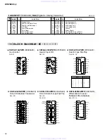
Page 51: ...older Module Stand SPAT1 WA59370 A2b Wing Bolt 5 0X10 MFZN2B3 WG69620 2 WH227900 WH228100 WH236000 WD232900 WH236400 WH236500 WH236600 WH236700 WH238000 WH021400 WH021500 WC322300 VQ664100 VG016600 WD345600 WE998100 WE774300 WF577000 MFA22060 WH323600 WH238500 V8028600 V8028700 V8028800 WF322000 WJ326700 総 組 立 総 組 立 ト ッ プ ケ ー ス 印 刷 品 フ ロ ン ト ケ ー ス 塗 装 品 ボ ト ム ケ ー ス 印 刷 品 レ ッ グ ボ タ ン K I T 印 刷 品 ボ ...

Page 52: ...61 Ceramic Capacitor B chip 0 0100 50V K RECT 01 65 Ceramic Capacitor B chip 0 0100 50V K RECT 01 C66 Ceramic Capacitor F chip 0 1000 25V Z RECT 01 68 Ceramic Capacitor F chip 0 1000 25V Z RECT 01 C69 Ceramic Capacitor SL chip 100P 50V J RECT 01 73 Ceramic Capacitor SL chip 100P 50V J RECT 01 C74 Monolithic Ceramic Cap F 0 220 25V Z RECT 01 C75 Ceramic Capacitor F chip 0 1000 25V Z RECT 01 C76 Mon...

Page 53: ...00 25V Z RECT 01 401 Ceramic Capacitor F chip 0 1000 25V Z RECT 01 C402 Electrolytic Cap chip 0 1 50V UWX1H0 01 C403 Electrolytic Cap chip 0 1 50V UWX1H0 01 C404 Ceramic Capacitor F chip 0 1000 25V Z RECT 01 C405 Ceramic Capacitor SL chip 220P 50V J RECT 01 408 Ceramic Capacitor SL chip 220P 50V J RECT 01 C409 Electrolytic Cap chip 47 16V 01 C410 Electrolytic Cap chip 47 16V 01 C411 Electrolytic C...

Page 54: ...C MX29LV400CBTC 70G FLASH ROM 4M 04 IC10 IC MR27V12800J TN P2ROM 128M PROGRAM WAVE IC11 IC SN74LV4052APWR MULTIPLEXER IC12 IC SN74LV4052APWR MULTIPLEXER IC13 IC S 80142ANMC JC3T2G SYSTEM RESET 01 IC14 IC UPC4570G2 E1 A OP AMP 01 IC15 IC AK4385ET DAC 03 IC16 IC HG73C205AFDV SWX00B 09 IC18 IC SN74LV74APWR D FF 01 IC19 IC NJM2903M TE1 OP AMP 01 IC20 IC NJM2903M TE1 OP AMP 01 IC21 IC SN74LV245APWR TRA...

Page 55: ...LED Green GL3EG8 SAVE ENTER 01 LD306 LED Red GL3HD8 TEMPO L 01 LD307 LED Green GL3EG8 TEMPO R 01 LD308 LED Display 3HSR11410B6 R1 Carbon Resistor chip 10 0K 63M J RECT 01 R2 Carbon Resistor chip 10 0K 63M J RECT 01 R3 Carbon Resistor chip 220 0K 63M J RECT 01 R4 Carbon Resistor chip 100 0K 63M J RECT 01 R5 Carbon Resistor chip 100 0K 63M J RECT 01 R6 Carbon Resistor chip 100 0 63M J RECT 01 R7 Car...

Page 56: ...4 Carbon Resistor chip 4 7K 63M J RECT 01 125 Carbon Resistor chip 4 7K 63M J RECT 01 R126 Carbon Resistor chip 3 3K 63M J RECT 01 R127 Carbon Resistor chip 3 3K 63M J RECT 01 R128 Carbon Resistor chip 470 0 63M J RECT 01 R129 Carbon Resistor chip 5 6K 63M J RECT 01 R130 Carbon Resistor chip 5 6K 63M J RECT 01 R131 Carbon Resistor chip 68 0 1 4 J TP 01 R132 Carbon Resistor chip 47 0K 63M J RECT 01...

Page 57: ...CT 01 R375 Carbon Resistor chip 10 0K 63M J RECT 01 R376 Carbon Resistor chip 100 0K 63M J RECT 01 R377 Carbon Resistor chip 120 0 63M J RECT 01 R378 Carbon Resistor chip 100 0 63M J RECT 01 R379 Carbon Resistor chip 120 0 63M J RECT 01 R380 Carbon Resistor chip 1 0K 63M J RECT 01 R381 Carbon Resistor chip 1 0K 63M J RECT 01 R382 Carbon Resistor chip 820 0 63M J RECT 01 R383 Carbon Resistor chip 8...

Page 58: ...ch EVQ 11Y 05B PAGE 01 SW307 Tact Switch SKRGAED010 01 SW308 Push Switch EVQ 11Y 05B SAVE ENTER 01 SW308 Tact Switch SKRGAED010 01 Z TH1 Protector Switch MINISMDC110F 16 2 02 TR1 Digital Transistor DTB123YK T146 01 3 Digital Transistor DTB123YK T146 01 TR4 Digital Transistor DTC123JKA TP 01 11 Digital Transistor DTC123JKA TP 01 TR12 Transistor 2SC2412K Q R S TP 01 TR13 Transistor 2SA1162 Y TE85R F...

Page 59: ... 10V 01 VY677600 VD303700 VD303700 VS053600 V9366600 VU172600 New Parts RANK Japan only デ ジ タ ル ト ラ ン ジ ス タ ト ラ ン ジ ス タ ト ラ ン ジ ス タ 二 連 ロ ー タ リ ー V R セ ラ ミ ッ ク 振 動 子 ツ ェ ナ ー ダ イ オ ー ド REF NO PART NO DESCRIPTION REMARKS QTY RANK 部 品 名 DM PN www xiaoyu163 com QQ376315150 9 9 2 8 9 4 2 9 8 TEL 13942296513 9 9 2 8 9 4 2 9 8 0 5 1 5 1 3 6 7 3 Q Q TEL 13942296513 QQ 376315150 892498299 TEL 13942296513 Q...
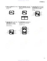
Page 60: ...P CN6 22P CN305 22P CN3 22P CN303 22P CN4 22P CN304 22P CN6 22P LD308 EC301 IC311 20P CN302 124 165 145 14 15 16 17 94 44 45 21 4 27 2 22 36 28 35 39 46 76 75 IC16 168P IC4 14P IC1 14P X1 IC13 5P IC10 48P 1 9 47 48 51 59 62 73 10 41 35 IC9 48P IC8 44P IC2 20P IC31 5P IC3 14P IC32 5P 12 26 11 28 41 6 93 17 101 88 40 39 90 95 4 4 1 2 1 2 132 131 10 9 8 11 119 130 129 128 151 152 133 143 161 125 127 ...

Page 61: ... AND GATE to DM 2 2 Page 2 M 9 to DM 2 2 Page 2 I 2 to DM 2 2 Page 2 B 9 to DM 2 2 Page 2 B 8 to DM 2 2 Page 2 K 2 to DM 2 2 Page 2 B 9 S BUS POWER P BUS POWER C BUS POWER 28CC1 2001009525 1 2 not installed DTC123JKA VY677600 DIGITAL TRANSISTOR DM TR4 11 1 GND 2 IN 3 OUT 1 3 2 OUT R1 R2 GND IN IN GND OUT DTB123YK VY677700 DIGITAL TRANSISTOR DM TR1 3 1 GND 2 IN 3 OUT 1 3 2 OUT R1 R2 GND IN IN GND O...

Page 62: ...01009525 2 1 180K 0 47u 180K 0 47u 180K 0 47u 180K 0 47u 180K 0 47u BA90BC0FP X8331A00 REGULATOR 9V DM IC26 1 INPUT 2 GND 3 OUTPUT 1 2 3 NJM78L05UA XJ598A00 REGULATOR 5V DM IC27 1 OUTPUT 2 GND 3 INPUT 1 2 3 NJM7805FA XJ607A00 REGULATOR 5V DM IC25 3 2 1 1 INPUT 2 GND 3 OUTPUT µPC29M33T E1 XU965A00 REGULATOR 3 3V DM IC28 1 INPUT 2 GND 3 OUTPUT 1 3 2 DA204K V3749000 DIODE ARRAY 2A X2 DM DA1 3 5 14 1 ...

Page 63: ...K 0 47u 180K 0 47u 180K 0 47u 180K 0 47u 180K 0 47u 金被 Metal Film Resistor 金属被膜抵抗 セ Ceramic Capacitor セラミックコンデンサー Note See parts list for details of circuit board component parts 注 シートの部品詳細はパーツリストをご参照ください DA204K V3749000 DIODE ARRAY 2A X2 PN DA301 317 1 CATHODE2 2 ANODE1 3 CATHODE1 ANODE2 1 3 2 1 2 3 MA2J732 VQ721800 DIODE PN D301 323 331 1 ANODE 2 CATHODE 2 1 1SS355 TE 17 VT332900 DIODE PN D302 3...

Reviews: