background image

  25

TRIG2


¡snare


0%

–Type=


TP1/SnrA‚

Previous page icon

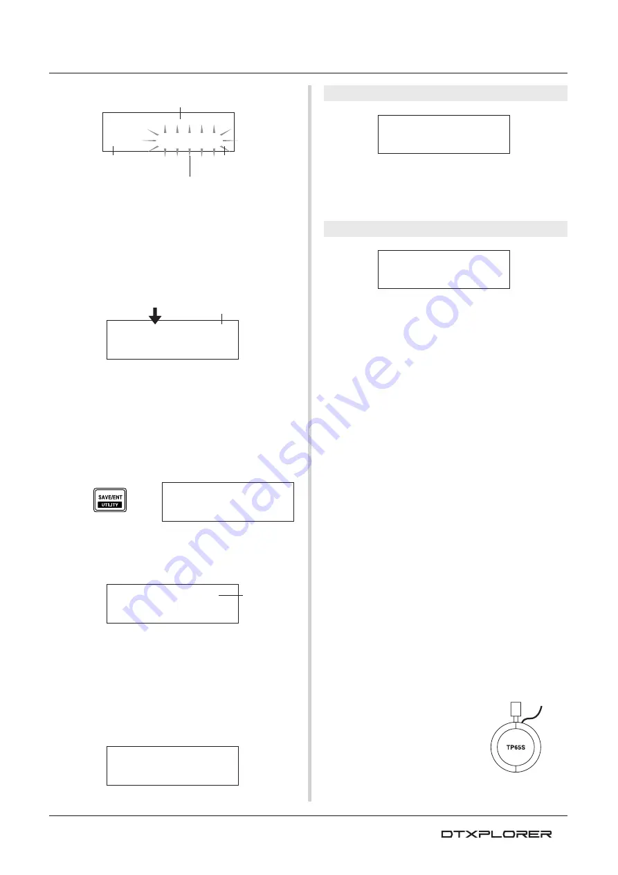
Trigger Input you want to edit

Next page icon

Flashing cursor
(the item you want to edit)


Completed!

3.

Rotate the jog dial to change the setting.

* An asterisk “

*

” will appear next to “

TRIG

” in the display if

data is changed. This asterisk will disappear after the store
operation is carried out.

* The Trigger Input Level produced when the pads are hit is

given on the upper right side in the display. When setting the
gain, use this level as a guide to measure how hard the
pads are being hit.

4.

To save changes you’ve made to the data, use the proce-
dure described below to store the data in User Trigger Setup
(No. 5).

* If a different trigger setup is selected before carrying out the

store operation, all changes you have made to the data will
be lost.

4-1. Press the [SAVE/ENT] button. The following display will

appear.

4-2. Press the [SAVE/ENT] button again and the following

display asking your confirmation to proceed with the store
operation.

4-3. Press the [SAVE/ENT] button to carry out the store op-

eration.

* To cancel the store operation, press any button except

for the [SAVE/ENT] and [SHIFT] buttons (when “Are you
sure?” appears in the display, the jog dial will also can-
cel the operation).

The following display appears after the store operation is
complete.

TRIG1 Trigger Setup Select

[Range] 1 to 5

Selects the Trigger Setup Type. (P. 24)

TRIG2 Type (Pad Type)

Sets the type of pad that is connected to the assigned input jack
shown in the upper half of the display ([1 SNARE] in the example
shown above).

* Values set in [TRIG3 Gain, MVl (Mininimum Velocity)] (P. 26)

and [TRIG5 SelfRejTime (Self Rejection Time)] (P. 26) will auto-
matically select the proper value for the pad type you set here.

Pad types are defined as follows.

KP

KP80S/80/65/60

TP1/SnrA

TP65S/65 (mainly used as a snare pad) 

*1

TP1/SnrB

TP65S/65 (mainly used as a snare pad) 

*1, *2

TP1/Tom

TP65S/65 (mainly used as a tom pad) 

*1

TP2-A

TP80S/80/65/60 

*3

TP2-B

TP80S/80/65/60 

*3

PCY1

PCY150S

PCY2

PCY130S/130

PCY3

PCY80S/80/65/60/10

RHH

RHH130

RHP


Pad

RHP120SD/120/100/80 (pad side) 

*4

RHP


Rim

RHP120SD/120/100/80 (rim side) 

*4

RHP


Kick

KP120

BP

BP80 

*5

DT


Snare

DT series drum trigger (for a snare drum)

DT


HiTom

DT series drum trigger (for small toms)

DT


LoTom

DT series drum trigger (for large toms)

DT


Kick

DT series drum trigger (for bass drum)

misc


1


to 

6

Another manufacturer’s pad 1 to 6.

*1 3-zone function (pad voice x1, rim voice x2) is available to a 3-

zone compatible pad such as the TP65S, etc., if it is connected
to the 1 SNARE input.

When connected to the 5 RIDE or 6 CRASH jacks, the rim will
produce only one voice. For produc-
ing closed rim shots, the [

TP1/

SnrA

] has a high sensitivity setting

on rim 1, while the [

TP1/SnrB

] has

a high sensitivity setting on rim 2.
Left and right rim sensitivity is set
at the same level for [

TP1/Tom

]. If

the pad is connected to any other
input, the rim voice will not be pro-
duced and the pad will only produce
one voice.

Rim 2

TRIG1

1


:Medium


TRIG2


¡snare


0%

–Type=


TP1/SnrA‚

Trigger Setup Edit

TRIG2*¡snare


0%

–Type=


TP1/SnrB‚

Trigger Input Level

TRIG


save


to


5

TRIG


save


to


5


Are


you


sure


?

Store
Destination

Rim 1

Summary of Contents for DTXPLORER

Page 1: ...DRUM TRIGGER MODULE Owner s Manual ...

Page 2: ...e rupture Warning Do not attempt to disassemble or incinerate any battery Keep all batteries away from children Dispose of used batteries promptly and as regulated by the laws in your area Note Check with any retailer of household type batteries in your area for battery dis posal information Disposal Notice Should this product become damaged beyond repair or for some reason its useful life is cons...

Page 3: ... sound quality or possibly cause overheating in the outlet Location Do not expose the instrument to excessive dust or vibrations or extreme cold or heat such as in direct sunlight near a heater or in a car during the day to prevent the possibility of panel disfiguration or damage to the internal components Do not use the instrument in the vicinity of a TV radio stereo equipment mobile phone or oth...

Page 4: ... May not be included depending on your particular area Please check with your Yamaha dealer NOTE The illustrations and LCD screens as shown in this owner s manual are for instructional purposes only and may appear somewhat different from those on your instrument About the descriptions This manual describes buttons and explanations using the following rules DRUM KIT CLICK etc The button on the top ...

Page 5: ...polyphony Voices include 192 drum and percussion voices Voices cover a wide range of sounds such as highly realistic acoustic sounds unique electronic percussion sounds effect sounds and much more Also featured is the same internal digital reverb section that is found inYamaha s MU series of GM XG compat ible tone generators High Performance Metronome The sound for each note value is adjustable Ea...

Page 6: ...With The Metronome 14 Click Out Select 16 Play Along With a Song 17 Tap Tempo Function 18 Using the Groove Check Function 19 Create Your Own Original Drum Kit 20 Factory Set 23 Trigger Setup Edit 24 Selecting the Trigger Setup 24 Editing the Trigger Setup 24 Error Messages 28 Trouble Shooting 28 Specifications 30 MIDI Data Format 31 MIDI Transmit Note Number 31 Display Global View 32 MIDI Implemen...

Page 7: ...ows editing is open Top Panel y Metronome ON OFF Button ON OFF This button is used to Start Stop metronome playback click sound P 14 Hold the SHIFT button and press the ON OFF button to enter the Tap Tempo Setting display P 18 u Save Enter Button SAVE ENT This button is used to carry out the command Enter or save data Hold the SHIFT button and press the SAVE ENT button to enter the Utility Mode wh...

Page 8: ...ck with a stereo cable the external pad input jack on the KP65 can be used as the input for Input jack 9 4 Hi Hat Controller Jack HI HAT CONTROL This jack is used to connect a hi hat controller P 9 Use a cable with a stereo plug shown below when connecting a Hi hat controller 5 Output Jacks OUTPUT L MONO R These jacks are used to connect the DTXPLORER to an external amplifier mixer etc For monaura...

Page 9: ...he jacks settings for sensitivity etc as described in the Trigger Setup Edit section P 24 should be changed CAUTION To prevent electric shock and damage to the devices make sure the power is switched OFF on the DTXPLORER and all related devices before making any connections to the DTXPLORER s input and output jacks The DTXPLORER can be played from an acoustic drum kit if the kit is fitted with an ...

Page 10: ...e AUX IN jack to mix the signal from the external source with the signal from the DTXPLORER The com bined audio can be sent on to an external device via the DTXPLORER s output jacks This jack can be used when you want to play along with a favorite tune or perform with friends Use the volume control on the external device CD player etc to adjust the volume balance Connections Some Advice On Connect...

Page 11: ...s connected to the DTXPLORER After the DTXPLORER s power is switched ON switch the other device s power ON MIDI OUT Jack The DTXPLORER s MIDI function lets you play voices on an external tone generator with the DTXPLORER s pads or synchro nize the DTXPLORER s song or metronome playback with the playback of an external sequencer About MIDI MIDI Musical Instrument Digital Interface is a world standa...

Page 12: ... the right to increase the overall volume to a comfort able volume level Rotating the knob to the right increases the volume level while rotating to the left decreases 3 Select A Drum Kit Each kit is made up of voices that are produced when a pad is hit Drum kit numbers 1 through 32 consist of 32 different types of preset drum kits that have been specially programmed by Yamaha sound designers Rota...

Page 13: ...nd easier to pro duce Too high a value will makes foot splashes too easy to produce resulting in the continuous production of foot splashes when the pedal is held down continuously UTIL1 Hi hat HHofs 0 T 0 UTIL1 Hi hat HHofs 12 T 0 UTIL1 Hi hat HHofs 12 T 20 Use the buttons in this manner to select the flashing cursor the item you want to set When the page only contains a single item pressing the ...

Page 14: ...Set Number Range 1 to 30 Selects the click set to be used Beat Range 1 to 9 Sets the click s time signature Tempo Range 30 to 300 Sets the click s tempo q The Tap Tempo Function can be used to set the tempo In this function hitting the pads in tempo sets the song or click s tempo This let s you set the tempo to any tempo you like Refer to page 18 for more information Timer Range off 30 to 600 seco...

Page 15: ...ew the Click Voice section on page 5 in the Click Setting Play Along With The Metronome CLK4 Sound 1 Metronome You can assign a different drum voice to each of the metronome s five click voices This setting is not available if the setting for CLK4 is set to anything other than UserClick First select the click value type A Œ in the upper half of the display then move the flashing cursor to the lowe...

Page 16: ...ceed with caution because carry ing out this operation will rewrite the DTXPLORER s entire contents all click sets user trigger setup No 5 user drum kits 33 to 42 with the data that was set in the unit s memory when it was shipped from the factory P 23 Click Out Select The DTXPLORER lets you select from which output jack the metronome s signal is delivered Click output and per formance output can ...

Page 17: ...value and flash This sets the volume for the parts other than the drum 0 to 16 Rotate the jog dial and adjust the balance between the song accompaniment and your performance SONG ƒ 120 2 Demo2 Song Name SONG ƒ 120 1 Demo1 Song Number The tempo can also be set using the Tap Tempo Function This function lets you set the song or metronome s tempo by tapping in tempo on a pad With this you can set the...

Page 18: ...um kit when playing along with the song press the DRUMKIT button to enter the Drum Kit Select display and then se lect another drum kit number If a different song is selected when the drum mute is active SHIFT SONG the drum kit will not change when a different song is selected Play Along With a Song Tap Tempo Function With the Tap Tempo Function you can set the song or metronome s tempo by tapping...

Page 19: ... 0 to 9 9 Timing display 1 Select a Song or a Click Set First select the song or click set that you want to play along with 2 Groove Check Display Press the SHIFT CLICK buttons to view the Groove Check s GRV1 main display Rotate the jog dial to set the song s or metronome s tempo q 30 to 300 3 Select the Pad Press the button to view page GRV2 then rotate the jog dial to select the pad Trigger Inpu...

Page 20: ...20 etc are used one Input Source will be as signed to one input jack When stereo pads TP65S 80S PCY65S 80S 130S etc are used two Input Sources pad input and rim switch input or 2 kinds of pad input etc will be assigned to one input jack When a 3 zone pad such as the TP65S PCY150S etc is used three Input Sources pad input and two rim switches etc will be assigned to one input jack To select the pad...

Page 21: ...w you ve selected the drum voice that will be used as the base for your original drum voice Next let s edit this drum voice and create an original bass drum voice 3 Change the Volume Try changing the volume that is produced by the drum voice when the pad is hit Use the volume setting to adjust the vol ume balance between other pad voices Use the button to view page KIT3 then rotate the jog dial to...

Page 22: ...f when the trigger for the next voice in the same alternate group is received after the open hi hat voice is switched off the closed hi hat voice sounds Use the button to view page KIT10 then rotate the jog dial to set the alternate group off 1 to 9 When this setting is set to off the mute will not be active Some voices such as the hi hat etc already have the alter nate group set in their preset s...

Page 23: ... Your Own Original Drum Kit 12 2 Rotate the jog dial to select the destination Drum Kit number 33 to 42 that you want to store the original drum kit in Data cannot be stored to Preset Drum Kit 1 to 32 12 3 Press the SAVE ENT button again and the following display asking your confirmation to proceed with the store operation 12 4 Press the SAVE ENT button to carry out the store op eration To cancel ...

Page 24: ...IT buttons to view page 1 in the Trigger Setup Select display TRIG1 2 Rotate the jog dial to select the trigger setup that matches the drum kit you are using TRIG1 2 Dynamic Trigger Setup Trigger Setup List TRIG1 1 Medium Editing the Trigger Setup If you are using pads or drum triggers other than those that came with your DTXPLORER or if you need to solve problems with double triggers or cross tal...

Page 25: ...jack shown in the upper half of the display 1 SNARE in the example shown above Values set in TRIG3 Gain MVl Mininimum Velocity P 26 and TRIG5 SelfRejTime Self Rejection Time P 26 will auto matically select the proper value for the pad type you set here Pad types are defined as follows KP KP80S 80 65 60 TP1 SnrA TP65S 65 mainly used as a snare pad 1 TP1 SnrB TP65S 65 mainly used as a snare pad 1 2 ...

Page 26: ...ge values will produce a high volume level even if the pad is hit softly However this will result in a narrow volume range making it difficult to adequately produce wider dy namic levels The trigger input level will be displayed as a in the upper right hand corner of the display The maximum velocity input level 99 will be 127 The level is low when the pad is hit the weakest so a wider dynamic rang...

Page 27: ...values will require a greater input level in order to produce a trigger event A from 56 setting assigns both trigger inputs 5 and 6 TRIG8 Copy to Input Trigger Setup Copy This function copies all data settings in pages TRIG2 Type Pad Type through TRIG7 SPRej Specified Rejection Level to an other input jack CAUTION When the Trigger Setup Copy operation is carried out the trigger setup data will be ...

Page 28: ...e Is the volume of the voice you want to use too low P 21 KIT3 Volume The trigger sound is not stable for acoustic drums Check the Produces sound but the sensitivity is too low volume is low list above Is the proper pad type set Select a larger pad type setting DT snare DT hi tom DT lo tom DT kick 1 DT kick 2 P 25 TRIG2 Type Pad Type Is the DT20 properly attached with sticky tape Is there any old ...

Page 29: ...he pad drum that is not producing sound P 26 TRIG3 Gain MVI Minimum Velocity Lower the rejection setting of the pad that is not producing sound P 26 TRIG6 Rejection Rejection Level Lower the specified rejection setting of the pad that is not producing sound P 27 TRIG7 SPRej Specified Rejection Level Are both pads set to the same alternate group P 22 KIT10 AltGroup Alternate Group The sound is alwa...

Page 30: ...mini jack Trigger Inputs 1 5 6 stereo phone jackmL trigger input R rim switch Trigger Inputs 2 3 4 7 mono phone jack trigger input Trigger Input 8 9 stereo phone jackmL R trigger input Power supply DC 12V AC adaptor Power Requirement 3 2 Watt Dimensions W x D x H 252 x 140 x 54 mm 9 15 16 x 5 1 2 x 2 1 8 Weight 835 g 1 lbs 13 oz Accessories Owner s Manual PA 3C AC power adaptor included or optiona...

Page 31: ...ecimal Sets all the data except the MIDI master tuning data to its initial value 3 System Realtime message 3 1 timing clock Sends data 3 2 start stop Sends data 3 3 active sensing Send the messages within an interval of approximately 300 msec MIDI Data Format Input Instrument Note Number 6 Clash 49 6 Clash edge 57 7 HI Hat open 46 7 HI Hat close 42 7 HI Hat foot close 44 7 HI Hat foot splash 85 8 ...

Page 32: ...32 Display Global View Opening Display P 12 P 12 P 17 Song Select Utility Settings P 13 P 16 P 18 P 13 P 17 P 23 Drum Kit Settings P 12 P 20 P 21 P 21 P 21 P 21 P 22 P 22 P 22 P 22 P 22 P 23 ...

Page 33: ...33 Display Over View Groove Check Function P 19 P 19 P 19 P 19 Tap Tempo Function P 18 Click Settings P 14 P 15 P 15 P 15 P 15 P 15 P 16 Trigger Setup Edit P 24 P 25 P 26 P 26 P 26 P 26 P 26 P 27 P 25 ...

Page 34: ...ystem Song Pos x Song Sel x Common Tune x System Exclusive o Prog o 0 127 Change True 0 4 7 10 32 o 1 6 11 64 x 71 72 73 x 74 84 91 x 100 101 x Control Change Pitch Bender x After Key s x Touch Ch s x Velocity Note ON o 9nH v 1 127 Note OFF x 9nH v 0 Note 0 127 Number True voice 0 127 Default x Mode Messages x Altered Basic Default 1 16 memorized Channel Changed 1 16 YAMAHA Drum Trigger Module Dat...

Page 35: ...2 HHDarkSp 13 HHOpen12 14 HHClse12 15 HHFoot12 16 HHSpls12 17 AnalogOp 18 AnalogCl 19 TechnoOp 20 TechinoCl P Percussion 1 Agogo Hi 2 Agogo Lo 3 BellTree 4 Bongo Hi 5 Bongo Lo 6 Claves 7 Conga Hi 8 Conga Lo 9 CongaSlp 10 CongaH S 11 Cowbell1 12 Cowbell2 13 Cowbell3 14 Cowbell4 15 DjembeSb 16 DjembeSl 17 DjembeEd 18 SWhistle 19 Shaker 20 SleiBell 21 StickHit 22 SurdoOpn 23 SurdoMut 24 SurdoM O 25 T...

Page 36: ...usantik Gedung Yamaha Music Center Jalan Jend Gatot Subroto Kav 4 Jakarta 12930 Indonesia Tel 21 520 2577 KOREA Yamaha Music Korea Ltd Tong Yang Securities Bldg 16F 23 8 Yoido dong Youngdungpo ku Seoul Korea Tel 02 3770 0660 MALAYSIA Yamaha Music Malaysia Sdn Bhd Lot 8 Jalan Perbandaran 47301 Kelana Jaya Petaling Jaya Selangor Malaysia Tel 3 78030900 PHILIPPINES Yupangco Music Corporation 339 Gil ...

Reviews: