background image

43

DPX-530

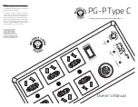
PRINTED CIRCUIT BOARD

FOR INFORMATION ONLY (NO REPLACEMENT PARTS WILL BE AVAILABLE)

R7Q1

R7Q2

SK

SS

SD

SN

SG

SM

SY

SP

SW

SX

SA

SZ

SJ

MAIN

D7M0

R7Q0

C4C0

D6U0

D8C0

D8C1

D8C2

D8C3

C2A2

C2A3

C2A4

C2A5

C2A6

C2A7

C2A8

C2B2

C2B3

C2B4

C2B5

C2C2

C2C3

C2D2

C2D3

C2D4

C2E2

C2F0

C2F1

C2F2

C2F3

C2F5

C2F6

C2F7

C2F8

C2F9

C2G0

C2G1

C2H1

C2H3

C2H4

C2J1

C2J4

C2K3

C2K4

C4A2

C4A3

C4A4

C4A5

C4A6

C4A7

C4A8

C4A9

C4B0

C4B1

C4B2

C4B3

C4B4

C4B5

C4B6

C4B9

C4C4

C6B0

C6F0

C6F1

R6B1

R6B2

C6L4

C6P5

C6Q1

C6Q2

C6R1

C6U0

C6U1

C7A0

C7A1

C7A2

C7A3

C7T0

C8C0
C8C1
C8C2
C8C3

C8C4

C8C5

C8C6

C8C7

C8C8

C8C9

C8D3

C4C5

C272

C273

C401

C402

C403

C404

C405

C406

C407

C408

C409

C410

C411

C412

C413

C414

C415

C417

C418

C420

C421

C422

C423

C424

C425

C426

C429

C430

C431

C432

C434

C435

C436

C437

C438

C439

C440

C441

C442

C443

C444

C445

C446

C447

C448

C449

C450

C451

C452

C453

C470

C471

C472

C473

C474

C481

C482

C483

C484

C490

C550

C570

C580

C585

C589

C680

C681

C682

C683

C685

C686

C775

C776

C777

C850

C851

C852

C853

C854

C855

C857

C858

C859

C860

C879

C881

C882

C883

C884

C885

L2E0

L2J1

L6M0

L6N0

L6P0

L6T0

L6T1

L6T2

L6T3

L6U0

L7A1

L7T0

L7T3

L7T5

L585

R2A2

R2A3

R2D2

R2D3

R2J0

R4B4

R4B7

R4C1

R4C2

R4C4

R6B0

R6F0

R6G0

R6G1

R6L0

R6L1

R6N2

R6R2
R6R3

R6T1

R6U0

R6U1

R6U2

R6U3

R6U4

R6U5

R6U6

R7A0

R7T0

R7T3

R7T4

R7T5

R7T6

R8C0

R8C1
R8C2

R8C3

R8C7

R8C8

R8C9

R8D0

R8D3

R552

R6C1

R6C2

R278

R400

R401

R402

R403

R405

R406

R407

R408

R409

R410

R413

R414

R415

R416

R417

R418

R419

R420

R437
R438

R439

R440

R441

R443

R444

R445

R446

R450

R451

R457

R458

R460

R461

R471

R472

R480

R481

R482

R490

R491

R492

R553

R554

R555

R556

R557

R558

R559

R580

R581

R584

R585

R586

R587
R588

R589

R655

R665

R675

R680

R681

R682

R683

R685

R686

R790

R796

R797

R798

R850

R851

R852

R853

R885

R886

R887

R888

R889

R452

R463

TP7503

TP7504

TP7513

TP7514

TP7523

TP7524

TP7533

TP7534

TP7543

TP7544

TP7553

TP7554

TP7563

TP7564

TPADB

TPADG

TPADR

TPAG5

TPAG6

TPDG1

TPDG3

TPDG7

TPDG8

ALFHS

ALFVS

CLAMP

COAST

IC4A3

CS3

GD11

GD12

GD13

GD14

GD15

GD61

GD62

GD63

LGZ

LRZ

LSYNC

OCLKB

P1CLK

P1DEN

P1FLD

P1HS

P1VS

P2CLK

P2FLD

P2H0

P2HS

P2J0

P2K0

P2VS

P6A1

P6L1

P7A1

P7M1

P7M2

P7M3

P7M4

P490

P860

PARK

PGZ

PIC480

PRZ

PW1

PW2

SD

A0

SOG

IC580

IC8C0

D480

IC4A4

Q6U7

IC4A2

IC470

IC471

IC589

R2H2

R2H3

R2H5

R4C0

R4C5

R4C6

R6H4

R6H5

R6M0

R6M1

R6M2

R6M3

R6M4

R6M5

R6N3

R404

R421 R422

R423

R424

R425

R426

R427

R428

R429

R430

R431

R432

R433

R434

R435

R436

Q6B1

IC550

IC850

IC6L0

S750

S751

S752

S753

S754

S755

S756

D750

D751

CBIN

CIN

CRIN

HSYNCZ

L_LIT

PIN2

PIN4

P_GOOD

SCL0

TPAD03

TPAP

TPCTL3

TPGAPWM2

TPKP

TPLEFT

TPM

TPMUTE

R465

TPP

TPR

TPUP

TPURES

UVFLAG

VBIRD

Y

VSYNCZ

YIN

L6B1

L7A2

L7T4

L851

R4C3

C2J2

TPD7A1

C8D0

C8D1

C400

C416

C433

C485

C486

C487

L7A0

L7A3

L7A4

L490

L2A0

L2B0

L2C0

L2D0

L2H0

L418

L448

L449

L480

R8C4

R8C5

R8C6

IC585

IC2H0

IC2J0

IC2K0

IC6L1

IC7M1

IC490

IC472

IC480

Q550

Q680

Q681

Q682

Q683

Q685

Q686

Q2D2

Q6B0

Q6U0

Q6U1

Q6U3

Q7T0

Q7T1

Q7T2

Q7T7

Q7T8

Q556

Q584

Q756

IC250

R466

R467

TST0

TST1

TST2

TST3

TST4

TST5

TST6

TST7

R6C3

C6C4

1

1

2

4

1

2

3

4

1

2

4

1

2

3

4

1

2

4

1

2

3

4

1

2

4

3

1

13

12

1

24

1

3

4

1

1

4

8

1

4

5

1

1

5

7

3

1

2

14

1

8

5

8

1

10

1

8

31

1

K

A

16

3

3

3

9

4

5

MENU

POW

AUTO

ENTER

DOWN

COMP

VIDEO

4

1

1

4

UL MARK

935B2920,0

1,2,3,4,5,6,7,8,9,0

,1,2

PWB-MAIN

C  211A74001

4

16

2

8

1

1

5

9

8

5

5

1

1

2

3

4

A

B

C

D

5

PCB-MAIN [SIDE B]

PCB-MAIN [SIDE B]

SYMBOL

NO.

ADDRESS

SYMBOL

NO.

ADDRESS

SYMBOL

NO.

ADDRESS

SYMBOL

NO.

ADDRESS

SYMBOL

NO.

ADDRESS

SYMBOL

NO.

ADDRESS

SYMBOL

NO.

ADDRESS

SYMBOL

NO.

ADDRESS

SYMBOL

NO.

ADDRESS

SYMBOL

NO.

ADDRESS

ALFHS

C – 2

ALFVS

C – 2

C272

D – 2

C273

C – 2

C2A2

C – 1

C2A3

C – 1

C2A4

C – 1

C2A5

C – 1

C2A6

C – 1

C2A7

C – 1

C2A8

C – 1

C2B2

C – 1

C2B3

C – 1

C2B4

C – 1

C2B5

C – 1

C2C2

C – 1

C2C3

C – 1

C2D2

C – 1

C2D3

C – 1

C2D4

C – 1

C2E2

C – 1

C2F0

C – 1

C2F1

C – 1

C2F2

C – 1

C2F3

C – 1

C2F5

C – 1

C2F6

C – 1

C2F7

C – 1

C2F8

C – 1

C2F9

C – 1

C2G0

C – 1

C2G1

C – 1

C2H1

C – 1

C2H3

C – 1

C2H4

C – 1

C2J1

C – 2

C2J2

C – 1

C2J4

C – 2

C2K3

C – 1

C2K4

C – 1

C400

B – 2

C401

B – 2

C402

B – 2

C403

B – 2

C404

B – 2

C405

B – 2

C406

B – 2

C407

B – 1

C408

B – 1

C409

B – 2

C410

B – 2

C411

B – 2

C412

B – 2

C413

B – 2

C414

B – 2

C415

B – 2

C416

B – 2

C417

B – 2

C418

B – 1

C420

B – 2

C421

B – 2

C422

B – 2

C423

B – 2

C424

B – 2

C425

B – 2

C426

B – 2

C429

B – 2

C430

B – 2

C431

B – 2

C432

B – 2

C433

B – 2

C434

B – 2

C435

B – 2

C436

B – 2

C437

B – 2

C438

B – 2

C439

B – 2

C440

B – 2

C441

B – 2

C442

B – 2

C443

B – 2

C444

B – 2

C445

B – 2

C446

B – 2

C447

B – 2

C448

B – 2

C449

B – 2

C450

B – 2

C451

B – 2

C452

B – 2

C453

A – 2

C470

C – 3

C471

C – 3

C472

C – 3

C473

C – 3

C474

C – 3

C481

A – 1

C482

A – 1

C483

A – 2

C484

A – 2

C485

A – 1

C486

A – 1

C487

A – 1

C490

A – 2

C4A2

A – 4

C4A3

A – 4

C4A4

A – 4

C4A5

A – 4

C4A6

B – 4

C4A7

B – 4

C4A8

B – 4

C4A9

B – 4

C4B0

A – 4

C4B1

A – 4

C4B2

A – 4

C4B3

A – 4

C4B4

A – 4

C4B5

A – 4

C4B6

A – 4

C4B9

C – 3

C4C0

A – 4

C4C4

A – 4

C4C5

B – 4

C550

D – 3

C570

C – 3

C580

C – 3

C585

C – 3

C589

C – 3

C680

D – 3

C681

D – 3

C682

D – 3

C683

D – 3

C685

D – 3

C686

D – 3

C6B0

C – 3

C6C4

C – 4

C6F0

C – 3

C6F1

C – 3

C6L4

C – 2

C6P5

C – 2

C6Q1

C – 2

C6Q2

C – 2

C6R1

C – 3

C6U0

D – 3

C6U1

D – 3

C775

D – 2

C776

D – 2

C777

D – 2

C7A0

D – 1

C7A1

D – 1

C7A2

D – 1

C7A3

D – 1

C7T0

A – 2

C850

A – 1

C851

A – 1

C852

A – 1

C853

A – 1

C854

A – 1

C855

A – 1

C857

A – 1

C858

A – 1

C859

A – 1

C860

A – 1

C879

B – 1

C881

B – 1

C882

B – 1

C883

B – 1

C884

B – 1

C885

B – 1

C8C0

B – 5

C8C1

B – 5

C8C2

B – 5

C8C3

B – 5

C8C4

B – 4

C8C5

B – 4

C8C6

B – 4

C8C7

B – 5

C8C8

B – 5

C8C9

B – 5

C8D0

B – 5

C8D1

B – 5

C8D3

B – 5

CBIN

C – 1

CIN

C – 1

CLAMP

C – 3

COAST

C – 3

CRIN

C – 1

CS3

B – 2

D480

A – 1

D6U0

D – 3

D750

C – 4

D751

C – 5

D7M0

D – 5

D8C0

B – 4

D8C1

B – 4

D8C2

B – 4

D8C3

B – 4

GD11

B – 4

GD12

B – 4

GD13

B – 3

GD14

B – 4

GD15

B – 3

GD61

D – 3

GD62

D – 4

GD63

D – 3

HSYNCZ

C – 3

IC250

D – 2

IC2H0

C – 1

IC2J0

C – 2

IC2K0

C – 1

IC470

C – 3

IC471

B – 3

IC472

C – 2

IC480

A – 1

IC490

A – 2

IC4A2

C – 3

IC4A3

B – 4

IC4A4

A – 4

IC550

D – 3

IC580

C – 4

IC585

C – 3

IC589

C – 3

IC6L0

C – 2

IC6L1

C – 2

IC7M1

A – 1

IC850

A – 1

IC8C0

B – 5

L

A – 4

L2A0

D – 2

L2B0

D – 1

L2C0

D – 1

L2D0

D – 1

L2E0

C – 1

L2H0

D – 2

L2J1

C – 2

L418

B – 1

L448

B – 2

L449

B – 2

L480

A – 1

L490

A – 2

L585

C – 3

L6B1

C – 3

L6M0

C – 2

L6N0

C – 2

L6P0

C – 2

L6T0

D – 2

L6T1

D – 2

L6T2

D – 3

L6T3

D – 3

L6U0

D – 3

L7A0

D – 1

L7A1

D – 1

L7A2

D – 1

L7A3

D – 1

L7A4

D – 1

L7T0

A – 2

L7T3

D – 3

L7T4

A – 5

L7T5

A – 5

L851

C – 1

LGZ

C – 4

LRZ

C – 4

LSYNC

B – 2

OCLKB

A – 2

– 4

P1CLK

C – 2

P1DEN

C – 2

P1FLD

C – 2

P1HS

C – 2

P1VS

C – 2

P2CLK

C – 1

P2FLD

C – 2

P2H0

C – 1

P2HS

C – 2

P2J0

C – 2

P2K0

C – 1

P2VS

C – 2

P490

A – 2

P6A1

C – 4

P6L1

C – 2

P7A1

B – 5

P7M1

A – 1

P7M2

C – 4

P7M3

D – 5

P7M4

D – 5

P860

C – 1

PARK

A – 3

PGZ

C – 4

PIC480

A – 2

PIN2

A – 4

PIN4

A – 4

PRZ

C – 4

PW1

C – 2

PW2

B – 2

Q2D2

C – 1

Q550

C – 3

Q556

D – 3

Q584

C – 3

Q680

D – 3

Q681

D – 3

Q682

D – 3

Q683

D – 3

Q685

D – 3

Q686

D – 3

Q6B0

C – 3

Q6B1

C – 3

Q6U0

D – 2

Q6U1

D – 2

Q6U3

D – 3

Q6U7

C – 3

Q756

A – 4

Q7T0

A – 2

Q7T1

A – 2

Q7T2

A – 2

Q7T7

A – 5

Q7T8

A – 5

R278

D – 2

R2A2

C – 1

R2A3

C – 1

R2D2

C – 1

R2D3

C – 1

R2H2

C – 1

R2H3

C – 1

R2H5

C – 2

R2J0

C – 1

R400

B – 1

R401

B – 1

R402

B – 1

R403

B – 1

R404

A – 2

R405

A – 2

R406

A – 2

R407

A – 2

R408

A – 2

R409

A – 2

R410

A – 2

R413

B – 2

R414

B – 2

R415

B – 2

R416

A – 2

R417

B – 2

R418

B – 2

R419

B – 2

R420

B – 2

R421

A – 2

R422

A – 2

R423

A – 2

R424

A – 2

R425

A – 2

R426

A – 2

R427

A – 2

R428

A – 2

R429

A – 3

R430

A – 3

R431

A – 3

R432

A – 3

R433

A – 3

R434

B – 3

R435

B – 3

R436

B – 3

R437

B – 3

R438

B – 3

R439

B – 3

R440

B – 3

R441

B – 2

R443

C – 3

R444

B – 3

R445

C – 3

R446

B – 2

R450

B – 2

R451

B – 2

R452

C – 2

R457

C – 2

R458

C – 2

R460

B – 2

R461

B – 2

R463

C – 2

R465

B – 2

R466

C – 2

R467

C – 2

R471

C – 3

R472

C – 3

R480

A – 2

R481

A – 2

R482

A – 2

R490

A – 2

R491

A – 2

R492

A – 2

R4B4

A – 4

R4B7

B – 4

R4C0

A – 4

R4C1

A – 4

R4C2

A – 4

R4C3

A – 4

R4C4

A – 4

R4C5

A – 4

R4C6

A – 4

R552

D – 4

R553

D – 3

R554

C – 4

R555

D – 4

R556

D – 3

R557

D – 3

R558

D – 3

R559

D – 3

R580

C – 3

R581

C – 3

R584

C – 3

R585

C – 3

R586

C – 3

R587

C – 3

R588

C – 3

R589

C – 3

R655

D – 3

R665

D – 3

R675

D – 3

R680

D – 3

R681

D – 3

R682

D – 3

R683

D – 3

R685

D – 3

R686

D – 3

R6B0

C – 3

R6B1

C – 3

R6B2

C – 3

R6C1

C – 4

R6C2

C – 4

R6C3

C – 4

R6F0

C – 3

R6G0

C – 3

R6G1

C – 3

R6H4

C – 3

R6H5

C – 3

R6L0

C – 2

R6L1

C – 2

R6M0

C – 3

R6M1

C – 3

R6M2

C – 3

R6M3

C – 3

R6M4

C – 2

R6M5

C – 2

R6N2

C – 2

R6N3

C – 2

R6R2

C – 3

R6R3

C – 3

R6T1

D – 3

R6U0

D – 2

R6U1

D – 2

R6U2

D – 2

R6U3

D – 2

R6U4

D – 3

R6U5

C – 3

R6U6

C – 3

R790

D – 2

R796

A – 4

R797

A – 4

R798

C – 3

R7A0

D – 1

R7Q0

D – 5

R7Q1

D – 5

R7Q2

D – 5

R7T0

A – 2

R7T3

A – 5

R7T4

A – 5

R7T5

A – 5

R7T6

A – 5

R850

A – 1

R851

A – 1

R852

A – 1

R853

A – 1

R885

B – 1

R886

B – 1

R887

B – 1

R888

A – 1

R889

A – 1

R8C0

B – 5

R8C1

B – 5

R8C2

B – 5

R8C3

B – 5

R8C4

B – 4

R8C5

B – 4

R8C6

B – 4

R8C7

B – 5

R8C8

B – 5

R8C9

B – 5

R8D0

B – 5

R8D3

B – 5

S750

C – 4

S751

C – 4

S752

C – 4

S753

C – 4

S754

C – 5

S755

D – 4

S756

D – 4

SA

D – 2

SB

B – 4

SC

B – 3

SCL0

C – 2

SD

D – 1

SDA0

C – 2

SG

A – 5

SJ

D – 2

SK

D – 3

SM

A – 2

SN

C – 5

SOG

C – 2

SP

A – 1

SS

A – 2

SW

B – 5

SX

D – 5

SY

D – 5

SZ

C – 5

TP7503

B – 4

TP7504

B – 4

TP7513

C – 4

TP7514

C – 4

TP7523

C – 4

TP7524

C – 4

TP7533

C – 4

TP7534

C – 4

TP7543

C – 5

TP7544

C – 5

TP7553

D – 4

TP7554

D – 4

TP7563

D – 4

TP7564

D – 4

TPAD03

C – 5

TPADB

C – 4

TPADG

C – 4

TPADR

C – 4

TPAG5

D – 4

TPAG6

D – 4

TPAP

C – 4

TPCTL3

C – 2

TPD7A1

C – 5

TPDG1

A – 4

TPDG3

C – 2

TPDG7

B – 4

TPDG8

C – 1

TPGAPWM2

A – 4

TPKP

C – 4

TPLEFT

C – 4

TPM

C – 4

TPMUTE

C – 4

TPP

C – 4

TPR

C – 4

TPUP

C – 4

TPURES

B – 4

TST0

A – 1

TST1

A – 1

TST2

A – 1

TST3

A – 1

TST4

A – 1

TST5

A – 1

TST6

A – 1

TST7

A – 1

UVFLAG

C – 1

VBIRDY

C – 1

VSYNCZ

C – 3

YIN

C – 1

Summary of Contents for DPX-530

Page 1: ... this manual to any individual or firm does not constitute authorization certification or recognition of any applicable technical capabilities or establish a principle agent relationship of any form The data provided is believed to be accurate and applicable to the unit s indicated on the cover The research engineering and service departments of YAMAHA are continually striving to improve YAMAHA pr...

Page 2: ...that leakage current be measured according to the following methods 1 Cold check With the AC plug removed from the AC 100 to 240 V place a jumper across the two AC plug prongs Turn the projector AC switch on Using an ohm meter connect one lead to the AC plug and touch the other lead to each exposed metal part metal cabinet screwheads metal overlays etc particularly any exposed metal part having a ...

Page 3: ...or and the AC supply point before any test service is performed on a LIVE chassis projector 2 Operation of this projector outside the cabinet or with the cover removed involves a shock hazard from the projector power supplies Work on the projector should not be attempted by anyone who is not thoroughly familiar with precautions necessary when working on high voltage equipment 3 When service is req...

Page 4: ...laced and ground the sheet Projector overview 1 FOCUS ring 2 ZOOM ring 3 Control panel 4 Air intake vent 5 Remote control sensor Front 6 Air exhaust vent 7 Air intake vent 8 Terminal board 9 Remote control sensor Rear 10 Air exhaust vent Control area 1 STANDBY ON button 2 AUTO SYNC button 3 D SUB DVI button 4 MENU button 5 STATUS indicator 6 POWER indicator 7 KEYSTONE ENTER button 8 VIDEO S COMP b...

Page 5: ... 5 ENTER button 6 MENU button 7 C TEMP COLOR TEMPERATURE button 8 AUTO button 9 IRIS button 10 GAMMA button 11 ASPECT button 12 Direction buttons 13 S VIDEO button 14 COMP COMPONENT button 15 VIDEO button 16 STANDBY button See the below for the picture quality adjusting buttons Important When you press a button on the remote control the buttons on the remote control will light up Wait approximatel...

Page 6: ...tilation grilles are clogged with dust or dirt The room temperature is high Clean the ventilation grilles Relocate the projector to a cooler place Remove any objects blocking the ventilation grilles Steady red Blinking green Abnormal when it occurs except while shutting down The protection circuit is working or the lamp is in an abnormal condition Wait until the STATUS indicator goes out then pres...

Page 7: ...15P Line 1 1 1 1 2 Control terminal Others RS 232C 8P For service person Operating temperatures 41 F 5 C to 95 F 35 C Rated voltage AC100 240V 50 60Hz Power consumption 3 5 A Dimensions 360 mm W 102 mm V 290 mm D Not including protrusions Weight 3 9 kg Others S video input Luminance signal Vp p 1 0 V 75Ω negative sync Chrominance signals Vp p 0 286 V 75Ω burst signal Video input Vp p 1 0 V 75Ω neg...

Page 8: ... BLUE CB 4 GND 5 GND 6 GND 7 GND 8 GND 9 10 GND 11 GND 12 DDC Data 13 HD CS 14 VD 15 DDC Clock 1 5 11 6 10 15 Pin No Spec Pin No Spec 1 DATA 2 13 2 DATA 2 14 5V Power 3 DATA 2 Shield 15 Ground 4 16 Hot Plug Detect 5 17 DATA 0 6 DDC Clock 18 DATA 0 7 DDC Data 19 DATA 0 Shield 8 20 9 DATA 1 21 10 DATA 1 22 Clock Shield 11 DATA 1 Shield 23 Clock 12 24 Clock 17 24 16 9 8 1 290 11 7 16 69 2 11 16 360 1...

Page 9: ...sage LAMP EXCHANGE will appear on the screen for one minute every 20 hours 1 thereafter When the lamp operation time exceeds 4000 hours 1 2 the projector automatically shuts off and can not be used until the lamp is replaced and the lamp operation time is reset 1 When LAMP MODE in the SETUP menu is set to CINEMA When it is set to BRIGHT this duration will be decreased 2 When LAMP MODE is set to BR...

Page 10: ...ke sure that the STATUS indicator is lit twice and the lamp operation time is reset successfully The projector doesn t turn on if the lamp cover isn t attached securely Be sure to reset the lamp operation time whenever you replace the lamp Do not reset the lamp operation time unless you replace the lamp This projector uses a lamp that contains mercury Disposal of the lamp or the projector with the...

Page 11: ...filter for this projector Not all 67 mm lens filters are compatible with this projector Attaching the lens cap Attach the supplied lens cap when not using the projector to prevent the lens from becoming dirty or damaged Insert the lens cap until it is securely placed It should make a clicking sound Important Do not force the lens cap onto the projector Make sure that the YAMAHA name on the lens ca...

Page 12: ...B ASS Y LOCATION Item No Part name q MAIN PCB ASS Y w TERMINAL PCB ASS Y e Lamp power unit r INLET PCB ASS Y t POWER PCB ASS Y y DMD PCB ASS Y u IRF PCB ASS Y i CW PCB ASS Y o MOTOR PCB ASS Y Fig 1 Table 1 1 2 3 4 5 6 7 9 8 ...

Page 13: ...ee screws b as shown in Fig 2 1 3 Remove the top case unit as shown in Fig 2 1 4 Remove the three screws c as shown in Fig 2 1 5 Remove the two screws d as shown in Fig 2 1 6 Remove the terminal cover ASS Y as shown in Fig 2 1 a x8 bx3 c x3 d x2 Terminal cover ASS Y The top case unit and the terminal cover ASS Y are secured together by the screws b Top case unit Fig 2 1 ...

Page 14: ...ard to board connector and then insert it securely When dust or dirt is attached inside of the board to board connector a band like line may appear in the reflected image 3 Removal of the exhaust duct ASS Y 1 Remove the top case unit following 1 Removal of the top case unit and terminal cover ASS Y 2 Remove the main shield following 2 Removal of the MAIN PCB ASS Y 3 Remove the three screws f as sh...

Page 15: ... shield as shown in Fig 2 3 5 Remove the two screws c as shown in Fig 2 3 6 Remove the cooling fan DMD as shown in Fig 2 3 6 Removal of the optical unit 1 Remove the top case unit following 1 Removal of the top case unit and terminal cover ASS Y 2 Remove the MAIN PCB ASS Y following 2 Removal of the MAIN PCB ASS Y 3 Remove the duct fan following 3 Removal of the exhaust duct ASS Y 4 Remove the mai...

Page 16: ...t the connector TD on the TERMINAL PCB ASS Y as shown in Fig 2 6 7 Remove the two screws a as shown in Fig 2 6 8 Remove the two screws b as shown in Fig 2 6 9 Remove the four screws c as shown in Fig 2 6 10 Remove the four screws d as shown in Fig 2 6 11 Remove the terminal holder pin jack shield and remo barrier as shown in Fig 2 6 12 Remove the two screws e as shown in Fig 2 6 13 Remove the term...

Page 17: ...cing the Lamp power unit follow the Procedure of lamp power unit replacement attached to the service parts 9 Removal of the INLET PCB ASS Y 1 Remove the top case unit and terminal cover ASS Y following 1 Removal of the top case unit and terminal cover ASS Y 2 Remove the MAIN PCB ASS Y following 2 Removal of the MAIN PCB ASS Y 3 Remove the main bottom shield following 4 Removal of the cooling fan l...

Page 18: ...top case unit and terminal cover ASS Y following 1 Removal of the top case unit and terminal cover ASS Y 2 Remove the MAIN PCB ASS Y following 2 Removal of the MAIN PCB ASS Y 3 Remove the one screw a as shown in Fig 2 10 4 Remove the IRF PCB ASS Y as shown in Fig 2 10 5 Remove the main bottom shield following 4 Removal of the cooling fan lamp 6 Remove the terminal ASS Y following 7 Removal of the ...

Page 19: ...n following 3 Removal of the exhaust duct ASS Y 4 Remove the main bottom shield following 4 Removal of the cooling fan lamp 5 Remove the optical unit following 6 Removal of the optical unit 6 Remove the three screws a as shown in Fig 2 12 7 Remove the DMD duct as shown in Fig 2 12 8 Remove the two screws b as shown in Fig 2 12 9 Remove the DMD radiator as shown in Fig 2 12 10 Disconnect the connec...

Page 20: ... Y as shown in Fig 2 13 9 Remove the CW PCB ASS Y as shown in Fig 2 13 10 Remove the two screws b as shown in Fig 2 13 11 Disconnect the connector ZE on the DMD PCB ASS Y as shown in Fig 2 12 12 Remove the CW unit as shown in Fig 2 13 13 Remove the two screws c as shown in Fig 2 13 14 Remove the frame cover as shown in Fig 2 13 15 Remove the three screws d as shown in Fig 2 13 16 Remove the light ...

Page 21: ...UNIT as shown in Fig 2 15 17 Removal of the motor unit 1 Remove the top case unit following 1 Removal of the top case unit and terminal cover ASS Y 2 Remove the MAIN PCB ASS Y following 2 Removal of the MAIN PCB ASS Y 3 Remove the duct fan following 3 Removal of the exhaust duct ASS Y 4 Remove the main bottom shield following 4 Removal of the cooling fan lamp 5 Remove the optical unit following 6 ...

Page 22: ...ape Twist the TD lead at least 7 times and tuck it at the back of the RD connector PB RD CN1 CN2 RE AM SN TD RD SA SD SX Run the RE CN2 lead Fig 3 1 Routing in the chassis ASS Y 1 Note The inner wires are clamped so that they do not come close to heat generating or high voltage parts After servicing route all wires in their original position 1 Clamp the lead wires along the Clamping Zone shown in ...

Page 23: ...Main shield Adjuster Insert the sensor in the hole Run the lamp lead inside the boss SX SY SK sensor with a tape Clamp the lead of the Note that the lead wire should not be caught in SJ SA SD SM SP SZ SN SW SG Fit the cable to the claw of the exhaust duct ASS Y Fig 3 2 Routing in the chassis ASS Y 2 ...

Page 24: ...DPX 530 24 DPX 530 Top shield Note that the SW and SZ leads should not be caught in when attaching the top shield Fig 3 3 Routing in the DLP ASS Y ...

Page 25: ...he projector at the same time When the reset command is accepted the STATUS LED will flash green two times Note1 It takes about 10 seconds for the projector to complete the process of resetting to the factory settings because the iris is fully opened in the process Upon completion of the reset process the STATUS LED will flash green two times Do not disconnect the AC cord while the STATUS LED is f...

Page 26: ...or each projector Improper change will cause incorrect colors Unique value Yes To select the remote control sensor to be enabled REMOTE POS AUTO FRONT REAR AUTO Both of FRONT and REAR sensors FRONT Front sensor only REAR Rear sensor only AUTO Yes Not used normally To make the gamma setting linear STRAIGHT GAMMA ON Pressing the ENTER button makes the gamma setting linear No Notes in displaying the ...

Page 27: ...attached RS 232C cable 2 Connect the power cable to the projector Make sure that the POWER indicator illuminates red 3 Start the PC and copy the ChangePwbMAIN_DPX 530 folder onto the desktop 4 Double click LvpAdjDataComm_v4_1 exe in the ChangePwbMAIN_DPX 530 folder to start the data transfer program 5 Click ChangeCommPort and select the port which is connecting the personal computer and projector ...

Page 28: ...EEPROM IC500 of the new terminal PCB ASS Y with that of the old terminal PCB ASS Y in order to use the existing DDC data with the new terminal PCB ASS Y Check the operation of the projector with the new terminal PCB ASS Y When the terminal PCB ASS Y has been changed properly the projector operates correctly ...

Page 29: ...ar on the right to the bottom select I accept and agree to be bound by all the terms and conditions of this License Agreement and click Next to continue the installation process 4 On the Select Installation Type screen select ALL and click Next to continue the installation process 5 When the installation is finished click Finish and reboot the PC A shortcut to DLP Composer TM Lite is created on th...

Page 30: ...arts initialization upon completion of download when the EEPROM is new Therefore do not turn off the projector immediately after the download is completed The STATUS LED keeps illuminating red during the initialization When the initialization is completed the POWER LED blinks alternately red and green If the projector is turned off during the initialization it resumes the initialization at the nex...

Page 31: ... XP operating system Monitor for personal computer RS 232C cable service component SVGA signal generator equivalent to VG 812 Program ROM LC12 Ver 1 8 exclusively for VG 812 RGB D SUB conversion cable Red scale signal for C W delay adjustment Test signal SVGA signal Vertical frequency 60 Hz NTSC 480i signal Vertical frequency 59 94 Hz The timing and patterns for the adjustment are as follows Progr...

Page 32: ...minal window in capital alphanumeric letters with keyboard and press the enter key 4 Writing the adjustment value The adjustment value entered using the above mentioned procedure will be saved in EEPROM automatically 5 Close the window Click the closing button placed at the upper right hand corner of the window to close the Hyper Terminal Close all the opening windows before closing Windows 95 98 ...

Page 33: ... the adjustment finishes the return command 00 5111 is displayed on the Hyper Terminal window The last three digits of the return command indicate the adjustment results of R G and B respectively from the left by 1 or 0 When the adjustment has succeeded 1 is displayed When it has failed 0 is displayed Possible causes of failures in the adjustment are errors on the PCBs wrong signals and wrong inpu...

Page 34: ... tags of the FUNCTION menu will be displayed 5 Press the ENTER button The FUNCTION menu will be displayed 2 Set the following items for the picture quality CONTRAST 0 BRIGHTNESS 0 COLOR TEMP MID 1 Project an image on the screen 6 Display the FUNCTION menu and select C W Delay The built in red pattern will be displayed Adjustment range 0 to 0359 Initial value 12 7 Adjust the value for correct red T...

Page 35: ...ar Increase the adjustment value to deepen the color to be adjusted and decrease it to lighten the color Optimum adjustment range reference x 0 313 0 010 y 0 329 0 015 Red Red Contrast 8 Enter the 50 adjustment command 00 801 to the Hyper Terminal window to adjust the red to be optimum Enter 99 99 to for optimum red 1 9 When the command is returned the setting value is automatically saved in the E...

Page 36: ...e failure LED failure Unplug and plug the power cable Unplug and plug the power cable Unplug and plug the power cable POWER MAIN INLET RD connector 9 pin STBY5 Z952 D750 D751 F9F1 Cooling fan power stopped Unplug and plug the power cable MAIN SP connector Reset Check Point PCB Reference LED Indication POWER 3 Red green alternately Red STATUS Cooling fan exhaust stopped Unplug and plug the power ca...

Page 37: ...inute Lamp goes out Auto Damaged lamp Manual Damaged lamp 10 Red Green flash STATUS Input signal is not displayed IIC bus failure of A D DECODER Unplug and plug the power cable IC6A0 IC2A0 11 Red Green alternately Green flash3 No power off for one minute after power on No power off for one minute after power on Auto 13 Green Green flash cycle 1s MAIN Warning indicated by the LED during stby The en...

Page 38: ...dialog window displays the information stored in the projector model name serial No software version etc and the service menu information Information displayed in this window depends on the selected models 2 Some PCs may not be able to connect to the right COM port In such cases press the Change COM PORT button to switch the COM port Refer to 4 Switching the COM port 3 Press any of the Warning His...

Page 39: ...ting over this file be sure to select Save As from File of the menu in Notepad to save the file The name of the file being displayed should be DataTemp txt 4 Pressing the Warning Clear button displays the confirmation message window which asks you whether you will clear the warning history data Press the OK button to clear the warning history data or the Cancel button to cancel clearing them 5 Pre...

Page 40: ...ted correctly NO YES YES NO YES NO Malfunction of IC400 or subsequent circuits Check the voltage waveform of connector SB SC Check the video signal circuit around IC400 and IC4A0 If the above voltage waveform is normal malfunction has occurred in the DMD PCB ASS Y CW PCB ASS Y or optical unit Replace the DMD PCB ASS Y CW PCB ASS Y Replace the optical unit Malfunction has occurred in the digital si...

Page 41: ...on t use a heat dissipation board as GND Power source system 2 Is the color wheel rotating Check around Z900 Q901 Q902 IC902 and PC951 NO NO NO NO YES YES YES YES POWER PCB ASS Y POWER PCB ASS Y Are the voltages of the pins No 1 to 3 of the RE connector 390V The lamp does not light Malfunction of the PFC circuit Check around IC901 and Q900 Malfunction of the LAMP POWER UNIT Is the voltage of the p...

Page 42: ...C6A3 C 2 C6A4 C 2 C6A5 C 2 C6B1 C 3 C6C0 C 2 C6C1 C 2 C6C2 C 2 C6C3 C 2 C6D0 C 2 C6D1 C 2 C6D2 C 2 C6D3 C 2 C6D4 C 2 C6D5 C 3 C6D6 C 3 C6D7 C 3 C6D8 C 3 C6D9 C 3 C6E0 C 2 C6E1 C 2 C6E2 C 2 C6E5 C 2 C6L1 C 4 C6L2 C 4 C6L3 C 4 C6M0 C 4 C6M1 C 4 C6M2 C 4 C6M3 C 3 C6M4 C 4 C6M5 C 3 C6N0 C 4 C6N1 C 4 C6N2 C 4 C6N3 C 4 C6N4 C 3 C6N5 C 3 C6N6 C 4 C6N7 C 3 C6N8 C 4 C6P0 C 4 C6P1 C 4 C6P2 C 4 C6P3 C 4 C6P4...

Page 43: ...C442 B 2 C443 B 2 C444 B 2 C445 B 2 C446 B 2 C447 B 2 C448 B 2 C449 B 2 C450 B 2 C451 B 2 C452 B 2 C453 A 2 C470 C 3 C471 C 3 C472 C 3 C473 C 3 C474 C 3 C481 A 1 C482 A 1 C483 A 2 C484 A 2 C485 A 1 C486 A 1 C487 A 1 C490 A 2 C4A2 A 4 C4A3 A 4 C4A4 A 4 C4A5 A 4 C4A6 B 4 C4A7 B 4 C4A8 B 4 C4A9 B 4 C4B0 A 4 C4B1 A 4 C4B2 A 4 C4B3 A 4 C4B4 A 4 C4B5 A 4 C4B6 A 4 C4B9 C 3 C4C0 A 4 C4C4 A 4 C4C5 B 4 C550...

Page 44: ... SYMBOL NO ADDRESS SYMBOL NO ADDRESS SYMBOL NO ADDRESS C221 A 4 C222 A 4 C306 B 3 C307 A 3 C308 A 3 C310 B 3 C330 B 3 C332 B 3 C334 B 3 C336 B 3 C338 B 3 C339 B 3 C350 B 3 C351 B 3 C354 B 4 C356 B 4 C357 B 4 C358 B 4 C391 B 2 C505 A 2 C506 B 2 C600 A 3 C601 A 3 C602 A 3 C603 A 3 C604 A 3 C605 A 3 C606 A 3 C607 A 3 C608 A 3 C609 A 3 C612 A 3 C613 A 2 C614 B 2 C615 B 2 C617 B 3 C618 A 3 C619 B 3 C62...

Page 45: ...2 C355 B 2 C359 B 2 C392 B 4 C500 A 4 C501 A 4 C502 A 3 C503 B 3 C504 A 3 C509 A 3 C510 A 3 C511 A 4 C610 A 3 C611 A 3 C621 A 2 C623 A 3 C624 A 3 C700 B 4 C702 A 5 C706 A 4 C709 A 4 C711 B 4 C712 B 4 C714 A 2 C716 A 5 C717 B 4 D200 A 2 D210 A 2 D220 B 1 D300 B 4 D301 B 4 D302 B 1 D303 A 1 D304 B 1 D305 B 1 D331 B 2 D501 A 3 D506 B 3 D507 B 3 D600 A 3 D601 A 3 D602 A 4 D603 A 2 D604 A 2 D605 A 3 D7...

Page 46: ... LIVE 250V T10AH 02 03 04 934C1380 1 2 3 A B C D E PCB POWER COMPONENT SIDE PCB INLET COMPONENT SIDE PCB IRF COMPONENT SIDE SYMBOL NO ADDRESS SYMBOL NO ADDRESS AM D 2 C7V1 D 3 C7V2 D 3 C900 A 2 C901 A 2 C902 A 2 C903 B 1 C904 C 1 C910 C 1 C914 C 2 C917 B 1 C952 D 2 C954 D 2 C955 D 2 C956 D 1 C957 C 2 C958 D 2 C960 C 1 C963 E 2 C964 C 2 C965 E 1 C966 E 1 C967 E 1 C9F1 B 3 C9F2 C 3 C9F3 B 3 C9F4 B 3...

Page 47: ...OLDER SIDE SYMBOL NO ADDRESS SYMBOL NO ADDRESS SYMBOL NO ADDRESS C900 A 2 C901 A 2 C902 A 2 C903 B 3 C904 C 3 C905 A 3 C906 A 3 C907 A 3 C908 A 3 C909 C 3 C911 A 3 C912 B 3 C915 A 3 C916 B 3 C918 A 3 C919 A 3 C950 C 3 C951 C 3 C952 D 2 C954 D 2 C956 D 3 C957 C 2 C959 C 3 C961 D 3 C962 D 3 C963 E 2 C965 E 3 C9F1 B 1 C9F2 C 1 C9F3 B 1 C9F4 B 1 D900 A 2 D901 B 2 D902 B 2 D903 A 3 D904 A 3 D905 A 3 D9...

Page 48: ...48 DPX 530 MEMO ...

Page 49: ...4 65 66 67 68 69 7O 1 2 3 4 5 6 7 8 9 10 1 1 12 13 14 15 16 17 18 19 20 21 2 2 23 24 25 26 27 28 29 30 31 32 33 34 35 36 37 38 39 40 41 42 43 44 45 46 47 48 49 50 51 52 53 54 55 56 57 58 59 60 61 62 63 64 65 66 67 68 69 70 1 2 3 1 2 3 4 1 2 3 4 5 1 2 1 2 3 4 5 6 7 8 9 1 2 3 4 5 6 7 8 9 10 11 12 13 14 15 16 17 18 1 9 20 21 22 23 24 25 26 27 28 29 30 31 32 33 34 35 36 37 38 39 40 41 42 43 44 45 46 4...

Page 50: ...16 17 18 19 2O 21 22 23 24 25 26 27 28 29 3O 31 32 33 34 35 36 37 38 39 4O 41 42 43 44 45 46 47 48 49 5O 1 2 3 1 2 3 3 Vs 2 GND 1 OUT 1 2 3 4 5 6 7 8 9 1O 11 12 13 14 15 16 17 18 19 2O 21 22 23 24 25 26 1 2 3 1 2 3 4 5 6 7 8 9 1O 1 2 3 4 5 6 7 8 9 1O 11 12 13 14 15 16 17 18 19 2O 21 22 23 24 25 26 27 28 29 3O 31 32 FB TXDM RXD PC TXD PC EARTH USB FB FB FB OPEN FB FB D D VCCUSB PSDT PC5 TXD_PC RXD_...

Page 51: ... QO17 71 QO18 72 QO19 73 QO2O 74 QO21 75 QO22 76 OGND 77 QO23 78 OVDD 79 AGND 8O RX2 81 RX2 82 AVDD 83 AGND 84 AVCC 85 RX1 86 RX1 87 AGND 88 AVDD 89 AGND 9O RXO 91 RXO 92 AGND 93 RXC 94 RXC 95 AVDD 96 EXT_RES 97 PVDD 98 PGND 99 RESERVED 1OO SCL 1 2 3 4 5 6 1 2 3 4 5 6 7 8 9 1O 11 12 13 14 15 16 17 18 19 2O 21 22 23 24 25 26 27 28 29 3O 31 32 1 GND 2 GREEN7 3 GREEN6 4 GREEN5 5 GREEN4 6 GREEN3 7 GRE...

Page 52: ...OUT 5 125 B_OUT 6 126 VDD 127 VSS 128 B_OUT 7 129 R_OUT O 13O R_OUT 1 131 R_OUT 2 132 R_OUT 3 133 R_OUT 4 134 R_OUT 5 135 R_OUT 6 136 R_OUT 7 137 G_OUT O 138 VSS 139 VDD 14O G_OUT 1 141 G_OUT 2 142 G_OUT 3 143 G_OUT 4 144 G_OUT 5 1 ST 2 GND 3 OUT 4 Vdd 1 2 3 4 5 6 7 8 9 1O 1 2 3 4 1 2 3 4 1 2 3 4 1 2 3 4 1 2 3 4 1 2 3 4 1 2 3 4 1 2 3 1 2 3 4 1 VC 2 VIN 3 GND 4 Vout 5 Sense 6 1 2 3 4 1 2 3 1 NC 2 A...

Page 53: ...14 P15 P16 P17 P18 P19 P26 P27 P28 P29 P3O R1 R2 R3 R4 R5 R12 R13 R14 R15 R16 R17 R18 R19 R26 R27 R28 R29 R3O T1 T2 T3 T4 T5 T12 T13 T14 T15 T16 T17 T18 T19 T26 T27 T28 T29 T3O U1 U2 U3 U4 U5 U12 U13 U14 U15 U16 U17 U18 U19 U26 U27 U28 U29 U3O V1 V2 V3 V4 V5 V12 V13 V14 V15 V16 V17 V18 V19 V26 V27 V28 V29 V3O W1 W2 W3 W4 W5 W12 W13 W14 W15 W16 W17 W18 W19 W26 W27 W28 W29 W3O Y1 Y2 Y3 Y4 Y5 Y26 Y27...

Page 54: ...r 14V TD 13OOmA AGND FAN ON VC DRAIN SOURCE CONTROL VCC V LGND BPR38CF OPEN BPR38CF Y1 12P DGND FG2 POW TMP AGND AUGND FGND GND V VO SENCE VO VIN PCB MAIN 2 3 SD FAN ON O 1A 1 2A 2 1A GND 7OOmA GND 4P 2P LIVE NEUT OUT IN GND POW TMP NPN RSIO AGND Vout 3P All All All NPN PNP digital transistors digital transistors are are DTC124EK UN2212 DTA124EK UN2112 unless specified otherwise unless specified o...

Page 55: ... OUTPUT CONTROL OUTPUT HD VD CVBS Y 27M 8bit ADC Digital I F C Cr Sync Sep Timing Clamp x 8 D A Clock Gene 42M X tal reference clock 3line comb 3D comb Motion Det A C C color decord TINT adjust Color adjust Vertical enhance LTI contrast adjust delay adjust ITU R656 encode 656 601 Format IIC BUS SCL SDA ID1 S N Dtector CCD alice 27M 4fsc 4M DRAM 27M 10bit ADC Cb MPX SW 32 31 6 7 94 92 90 42 50 51 7...

Page 56: ... SYNC CONTROL HSCTL C HSYNC IN VIDEO IN VSEPA VSYNC IN CVPOL CVEXI CPSEL GND POLH EXIH POLV EXIV Vcc HDRV CLAMP VDRV CPWID IC560 BA7078AF IC5A0 MC74HC4538ADTR2 PIN 16 VCC PIN 8 GND RX AND CX ARE EXTERNAL COMPONENTS PIN 1 AND PIN 15 MUST BE HARD WIRED TO GND Q2 RESET 2 B2 A2 TRIGGER INPUTS Q2 15 14 12 11 13 10 9 FUNCTION TABLE Inputs Outputs Reset A B Q Q H H H L H X L Not Triggered H H X Not Trigg...

Page 57: ...7 70 77 57 64 123 124 125 127 126 2 MUX MUX MUX MUX MUX MUX SERIAL REGISTER AND POWER MANAGEMENT REF SYNC PROCESSING AND CLOCK GENERATION CLAMP CLAMP CLAMP IC6A0 AD9883AKST 110 Configuration Logic HDCP Decryption Engine HDPC Kyes EEPROM Registers I2C Slave Panel Link TMDS DIGITAL Core XOR Mask Panel Interface Logic 24 encrypted data unencrypted data 24 control CTL3 QE 23 0 QO 23 0 ODCK DE HSYNC VS...

Page 58: ... 2 VIN 1 REF VC VO Sense GND 5 3 4 TSD 2 VIN 1 REF VC VOUT Sense GND 5 3 4 TSD IC6U0 24LC02BT SN WP HV Generator I O Control Logic Memory Control Logic XDEC EEPROM Array Page Laches YDEC Sence Amp R W Control I O SCL Vcc Vss SDA 8 4 7 5 6 ...

Page 59: ... Q Function L X X X L Clear L L H H H H H H L H Q n n Q No change X Don t care CK CLR Q1 1 9 2 4 D1 CK Q D R 3 1 Q Q2 7 5 D2 CK Q D R 6 2 Q Q3 10 12 D3 CK Q D R 11 3 Q Q4 15 13 D4 CK Q D Q Q Q R 14 4 Q CK Q D R CK Q D R Q PCB MAIN 2 3 IC4A4 NL17SZ00DFT2 VCC B A 1 2 3 5 4 GND Y Input FUNCTION TABLE B L H L H Output Y AB Y H H H L A L L H H ...

Page 60: ...Bits 0 7 First MSB Shot One Latch and Logic SAR R Bits 0 7 REF Decoder and Ladder EN Flip Flop EVEN DIF 15 14 12 16 18 17 1 13 2 3 4 5 6 7 8 9 2 VIN 1 REF VC VO Sense GND 5 3 4 TSD 2 VIN 1 REF VC VOUT Sense GND 5 3 4 TSD IC7A1 SI 3020KM TL IC7M1 IC7M2 IC7M3 IC7M4 SI 3050KM TL IC7M0 M62343FP 4 Vcc LD 8 CLK 7 D1 6 GND 5 1 A01 2 A02 8 3 A03 8 Bit Latch 8 Bit Upper Segment R 2R 8 Bit Upper Segment R 2...

Page 61: ...ers Sense Amps Shift Registers Data In Storage High Voltage Timing Control State Counters Function Table H HIGH Logic Level L LOW Logic Level Inputs Output B Y L L L L L H H A B GND Y Vcc H A L H H L 1 2 3 5 4 IC471 NC7SZ08P5X PCB MAIN 3 3 Function Table H HIGH Logic Level L LOW Logic Level Inpu t S Function B0 Connected to A B1 Connected to A B1 GND B0 A Vcc S H L 1 2 3 4 5 6 IC473 IC474 NC7SB315...

Page 62: ... Sense Amplifier 5V M1 M2 BS SW GND 1 3 4 Current Comparator S R Q Q FB 5 1uA 1 8V 0 7V IC495 MBM29LV160BE90TN K HC900 RY BY RY BY Delete Circuit Controler Comand registor Writere Tip enable Output enable I O Buffer Data latch Y Decorder Y Gate 8 388 608 Cell Matrix X Decoder WR Delete Pull Timer Address lat DQ0 DQ15 STB A0 A18 A1 Low Vcc Detector WE BYTE RESET Vcc Vss CE OE STB 75 27 46 11 47 12 ...

Page 63: ...00 DPX 530 BUSCLK STOP PD FS 0 1 Refclik Multi 0 1 Pclk M Synclk N GND Test MUX Bypass MUX Phase Aligner PLL B A PAclk GND BUSCLKT BUSCLKC 11 12 23 24 2 14 15 6 7 13 18 20 Bypclk PLLclk Phase Detector IC850 ICS9212DF 03 ...

Page 64: ...ters DC Voltage VOLUME SEDIFF SEMAX CLK LIN1 LIN2 LIN1 LIN2 Rout Rout PVcc PVcc Vcc Gnd Bypass 5vREF SE BTL Lout Lout 5 7 4 6 23 22 3 20 10 12 9 12 27 1 2 17 8 15 18 24 21 16 14 26 Shutdoun 25 IC390 SI 3090KM TL 2 VIN 1 REF VC VO GND 5 3 4 TSD 2 VIN 1 REF VC VOUT Sense GND 5 3 4 TSD IC500 24LCS21AT SN SDA SCL 4 VSS 8 VCC WP 3 5 6 VCLK 7 I O CONTROL LOGIC MEMORY CONTROL LOGIC XDEC EEPROM ARRAY PAGE...

Page 65: ...2 IN1 A IN0 B 12 3 G 1 or 2 10 5 G 1 or 2 6 IN1 B IN2 A IN2 B SEL A B OE 20 OUT 0 18 OUT 1 16 OUT 2 22 23 Output Enable VCC VEE GND 6 13 14 17 21 24 7 15 19 2 4 9 11 IC700 ISL83220ECVZ T GND 14 Vcc 16 T1out 5kΩ 15 3 7 13 8 1 9 2 4 5 6 11 C1 C1 C2 C2 Vcc V V Rin T1in R1out EN 1 2 3 4 5 6 S Vcc Z GND Io I1 1 0 IC502 IC503 NC7SZ157P6X ...

Page 66: ...50A545O10 Z 7 AAX70400 TERMINAL COVER ASS Y 761B440O10 35 AAX70630 SEMS BIND HEAD SCREW 3x6 669D329O10 36 AAX70680 BIND HEAD TAPPING SCREW 3x8 BL 669D359O20 37 AAX70640 SEMS BIND HEAD SCREW 3x10 BL 669D460O40 42 AAX70700 BIND HEAD TAPPING SCREW 4x12 669D715O10 x3 x3 x2 x4 x8 1 7 35 x1 42 42 36 37 37 CHASSIS ASS Y 1 ...

Page 67: ...935B292O08 Z 8 AAX70530 LAMP FAN BM6025 04W B59 288P270O10 Z 9 AAX70220 DMD FAN 288P269O10 Z 11 AAX70410 EXHAUST DUCT ASS Y 622B024O10 33 AAX70670 BIND HEAD TAPPING SCREW 3x10 669D220O30 35 AAX70630 SEMS BIND HEAD SCREW 3x6 669D329O10 41 AAX70650 SEMS BIND HEAD SCREW 669D571O10 x8 x2 x5 x3 x2 x3 x2 x5 x8 35 35 35 33 9 8 33 11 33 41 3 4 33 41 CHASSIS ASS Y 2 TERMINAL ASS Y OPTICAL UNIT ...

Page 68: ...METIC COVER 752C273O80 Z 2 AAX70450 LAMP POWER UNIT AC 380 290P127O10 Z 8 AAX70260 P C B ASS Y INLET 934C138O01 Z 11 AAX70280 P C B ASS Y POWER 935B291O01 Z 16 AAX70250 P C B ASS Y IRF 935D787O01 32 AAX70660 BIND HEAD TAPPING SCREW 3x8 669D220O20 34 AAX70600 HEXAGON HEAD SCREW 4x10 669D245O20 35 AAX70630 SEMS BIND HEAD SCREW 3x6 669D329O10 38 AAX70690 BIND HEAD TAPPING SCREW 669D522O60 41 AAX70650...

Page 69: ...70350 FLEXIBLE FLAT CABLE YFB05 5001 50A 50P 243C335O10 AAX70360 FLEXIBLE FLAT CABLE 32P 243C336O10 35 AAX70630 SEMS BIND HEAD SCREW 3x6 669D329O10 36 AAX70680 BIND HEAD TAPPING SCREW 3x8 BL 669D359O20 39 AAX70610 JACK SCREW NO4 40UNC 11 8 669D535O10 40 AAX70620 JACK SCREW 669D535O20 41 AAX70650 SEMS BIND HEAD SCREW 669D571O10 35 36 41 2 39 40 x4 x4 x2 x2 x2 ...

Page 70: ...D084O70 13 AAX70510 LIGHT PIPE 499D085O30 14 AAX70560 LENS UNIT 499D084O20 Z 19 AAX70300 P C B ASS Y MOTOR 499D084O40 20 AAX70500 MOTOR UNIT 499D084O30 x4 x2 x1 x2 x2 x2 x3 x3 x4 x1 x2 x1 x1 x2 8 10 20 11 14 19 5 7 13 Note Special supply part As this part is manufactured as a special order the total quantity in stock is limited 30 units and no additional procurement is available Therefore this par...

Page 71: ... 1pc 246C479O10 207 AAX70320 RGB CABLE for PC 1 5m 1pc 246C521O10 208 AAX70460 FERRITE CORE RFC 9 BK 410C058O10 The following accessories are provided with this projector Check to be sure that all of the accessories are packed in the package Cables S video cable RGB cable for PC RS 232C cable Used for adjustment by service person Power supply parts Remote control parts Others mini D SUB 15 pin min...

Page 72: ...DPX 530 DPX 530 ...

Reviews: