


Getting Star
ted
3
DM1000 Editor—Owner’s Manual
Channel Select:
These options determine whether or not channel selection is linked. When the
PC->Console option is on, selecting a channel in DM1000 Editor selects the same channel on the
console. When the Console->PC option is on, selecting a channel on the console selects the same
channel in DM1000 Editor.
Confirmation:
These options determine whether or not a confirmation dialog box appears
when storing, recalling, or patching.
Layer Select:
These options determine whether or not Layer selection is linked. When the
PC->Console option is on, selecting a Layer in DM1000 Editor selects the same Layer on the con-
sole. When the Console->PC option is on, selecting a Layer on the console selects the same Layer
in DM1000 Editor.
Window Control from Console:
This option determines whether or not using the USER
DEFINED KEYS on the console enables you to remotely open and close the DM1000 Editor win-
dows.
Level Meter:
This option determines whether or not the level meters in DM1000 Editor are
enabled.
❏
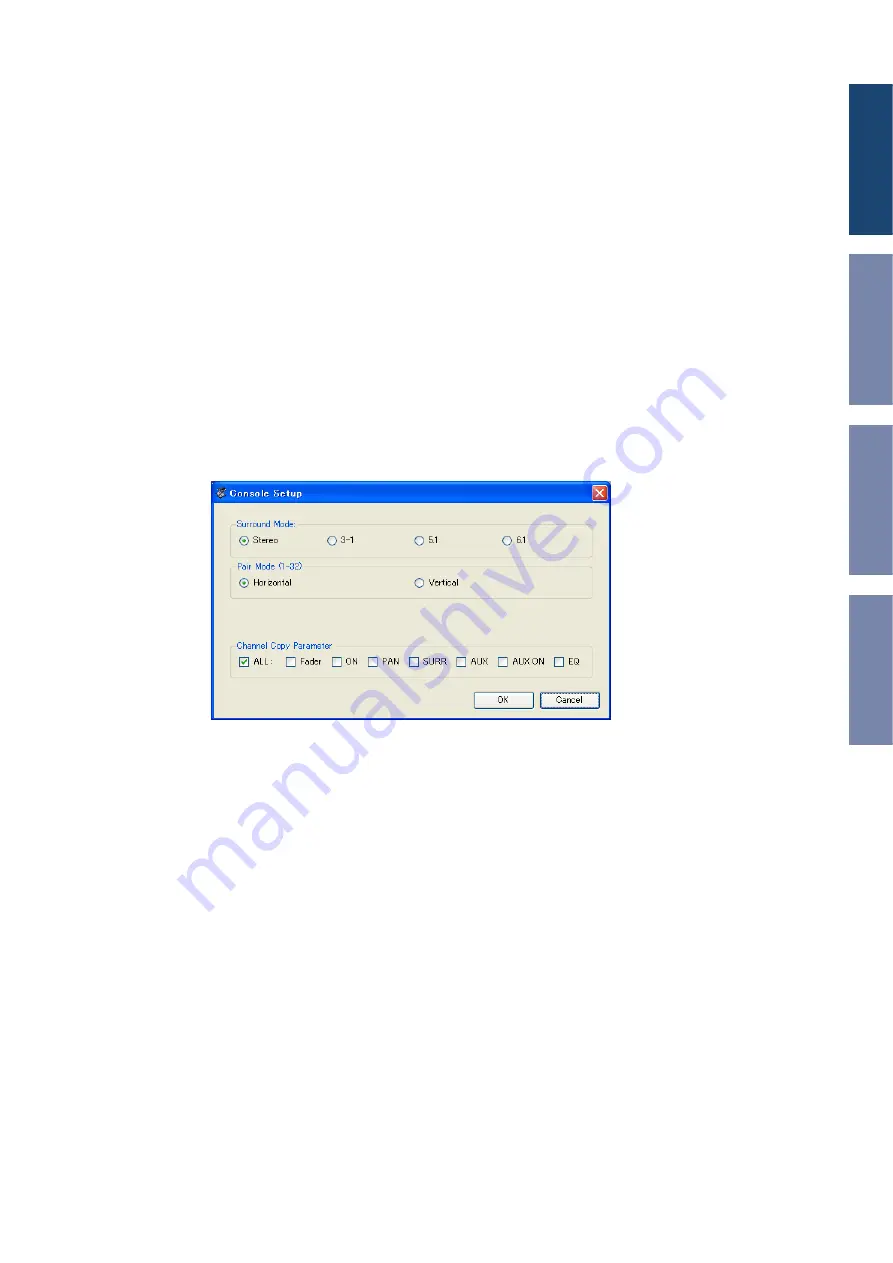
Console Setup
To open the Console Setup window, choose [Console Setup] from the [File] menu.
Surround Mode:
Select a Surround mode from STEREO, 3-1, 5.1, and 6.1.
Pair Mode:
These options determine whether the fader pair is Horizontal or Vertical.
Channel Copy Parameter:
Select desired parameters to copy from channel to channel.


