background image

17

Using the DG60FX-112

Create and Store a Patch

Original settings can be stored in the USER AREA
(011-933). Try creating an original patch and then
store it.

Storing Procedure

1. Press the [STORE] button.

When you enter the Store Mode, the display, the

[STORE] lamp and the foot switch lamp corre-

sponding to the patch number will flash.

2. Select the patch (group, bank, patch number) to

which you want to store the patch.

Use the same procedure as described in [Try

Selecting Another Patch] (page 15) to select a

patch. You can use the [UP]/[DOWN] buttons, the

foot switches and the BANK switch to select the

patch number. However, you cannot change the

AREA (it can only be assigned to the USER

AREA).

3. After select the patch you want to store your

patch in, hold the [STORE] button.

The store operation is complete when all lamps

light.

* Utility mode settings are not stored with patch data. As com-

mon settings for all patches, their contents are stored in the
DG60FX-112 memory.

* The OUTPUT knob’s setting is not stored with the patch data.

Use the MASTER knob to set differences in volume for situa-
tions like backing, soloing, etc.

* Data in the USER AREA (011-933) can be stored in an exter-

nal MIDI device. (

 page 24)

This procedure can be used to store original patches
and also used to rearrange the order of patches for
use during live performance.

Convenient Functions

Here are some convenient functions that you can
use with the DG60FX-112.

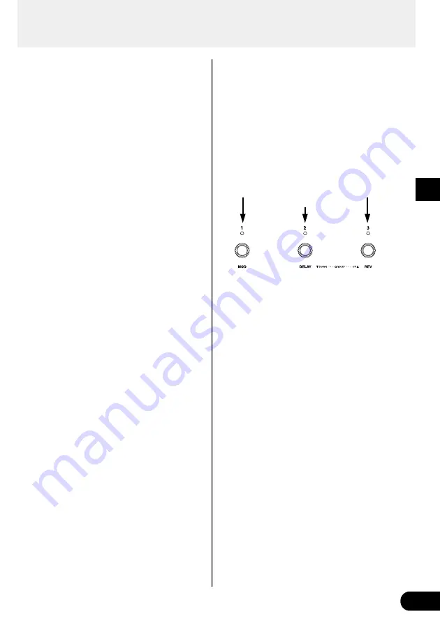
Use Foot Switches 1-3 to Switch Ef-
fects ON/OFF

You can set Foot Switch 1 to act as an ON/OFF
switch for the modulation effect, Foot Switch 2 as
an ON/OFF switch for the delay effect, and Foot
Switch 3 as an ON/OFF switch for the reverb effect.

1. Press the [UTILITY] button and set the amp se-

lect switch to the LEAD 1 position.

After entering the Utility Mode, “

F.S

” will appear

on the display and then the currently selected

foot switch function will be displayed.

PrG

: Select a patch

EFF

: Switches the effect block ON/OFF

2. Use the [UP]/[DOWN] buttons to set the foot

switch function to “

EFF

”.

3. Press the [UTILITY] button to return to the Play

Mode.

4. Press Foot Switches 1-3 to switch the corre-

sponding effect block ON/OFF.

* To change the Bank, Group or Area, press and hold the BANK

switch until the display and the Foot Switch lamp flashes. (

page 16)

Modulation

Effect

Delay

Effect

Reverb

Effect

Summary of Contents for DG60FX-112

Page 1: ...Owner s Manual ...

Page 2: ...a Corporation of America Electronic Service Division 6600 Orangethorpe Ave Buena Park CA90620 The above statements apply ONLY to those products distributed by Yamaha Corporation of America or its subsidiaries This applies only to products distributed by YAMAHA CORPORATION OF AMERICA This applies only to products distributed by Yamaha Canada Music Ltd Ceci ne s applique qu aux produits distribués p...

Page 3: ...nstalled in locations that do not seriously contribute to their operating temperature Placement of this product close to heat sources such as radiators heat registers etc should be avoided 8 This product was NOT designed for use in wet damp locations and should not be used near water or exposed to rain Examples of wet damp locations are near a swimming pool spa tub sink or wet basement 9 This prod...

Page 4: ...dphones 11 Digital Output 11 Connecting an Expression EXP Pedal 11 Connecting MIDI Devices 11 Using the DG60FX 112 12 Produce Sound 12 Try Changing the Settings 13 Try Selecting Another Patch 15 Create and Store a Patch 17 Convenient Functions 17 Effect Functions and Parameters 19 External Control Settings 21 Tuner Mode 22 How to Enter the Tuner Mode 22 Tuning 22 Setting the Standard Pitch 22 Util...

Page 5: ...ely cold or hot locations Locations exposed to high humidity or excessive dust Locations subject to strong shocks or vibration Before making any connections make sure that the power is switched OFF on the DG60FX 112 and any external devices To protect speakers from possible damage always set the OUTPUT knob to 0 before switching the power ON OFF When connecting a speaker to this unit make sure tha...

Page 6: ...ute volume of the tone wet with the Gain Volume and Tone Controls The MASTER knob s setting is saved in memory y Tone Controls TREBLE MIDDLE BASS PRESENCE Controls the sound level of each tone u Output Level Control OUTPUT Controls the output level of the LINE OUT jack PHONES jack and the speaker of the DG60FX 112 The OUTPUT knob s setting is not saved in the memory i Speaker Simulator Button SP S...

Page 7: ...ARY TREMOLO These buttons set the type of Modulation Effect to be used The selected effect s lamp will light A secondary parameter for the effect can be set by turning the SPEED or DEPTH knob while holding the button of the currently selected effect 8 Speed Knob SPEED Sets the Speed parameter and a secondary param eter of the Modulation Group s Effects 9 Depth Knob DEPTH Sets the Depth parameter a...

Page 8: ...llow the connection of an external effector between the LINE OUT Jack 8 and the POWERAMP IN Jack page 10 When a cable is connected to this jack the sound produced by the guitar connected to the INPUT jacks q will not be produced by the speaker The PHONES jack 7 does not reproduce the signal received by the POWER AMP IN jack The sound of the guitar con nected to the INPUT jacks q can be heard in th...

Page 9: ... until the Foot Switches 1 3 and Bank Switch lamps and the display on the main unit flashes Use the foot switches 1 3 to change the Area Group Bank page 16 Hold the switch until tu appears in the dis play The Foot Switch 1 3 and Bank Switch lamps all go off Enters the Tuner Mode page 22 6 EXP Pedal Jack EXP PEDAL Connect a foot controller expression pedal op tional such as the YAMAHA FC 7 etc to t...

Page 10: ...it between the LINE OUT jack and POWER AMP IN jack If the external effector is a monaural input type use the DG60FX 112 s L MONO LINE OUT jack when connecting the effector Special Cable The DG60FX 112 s speaker reproduces the sig nal from the L LINE OUT jack By connecting an external power amp and speaker to the R LINE OUT jack you can use the external unit in combination with the DG60FX 112 as a ...

Page 11: ...ck cannot be con trolled with the OUTPUT knob fixed Connections Connecting an Expression EXP Pedal A foot controller expression pedal such as the YAMAHA FC 7 connected to the EXP PEDAL jack on the Foot Switch Unit of the DG60FX 112 allows control of the DG60FX 112 s individual parameters or use as a wah pedal See pages 21 25 Connecting MIDI Devices Using the MIDI IN OUT jacks allows the exchange o...

Page 12: ...cted accidents like damage to your hearing due to a high volume setting 3 A 3 digit number such as 011 will appear on the display Note When the patch s number is shown on the display the device is in a condition called the PLAY MODE When in the PLAY MODE it is possible to select a patch and use the knobs or buttons to change settings to play For now use this patch to try and produce some sound 4 P...

Page 13: ...he lamp will light How ever only one effect per block can be used at a time Also if a button that is lit ON is pressed the light will go off and the effect in that block will be switched OFF All knobs can be used to set the parameters of the effect selected in the block Refer to Effect Functions and Parameters page 19 for more information on each effect s function or knob s setting The operation o...

Page 14: ...ou like 1 Simultaneously press the SP SIM button and the UTILITY button After SP S appears in the display the currently selected simulation type will be displayed The four types of simulation are as follows A42 American Style 12 inch x4 b42 British Style 12 inch x4 m42 Modern 12 inch x4 Y42 YAMAHA 12 inch x4 H42 Hybrid 12 inch x4 A22 American Style 12 inch x2 b22 British Style 12 inch x2 m22 Moder...

Page 15: ...groups 0 9 BANK Each group is divided into 3 banks 1 3 PATCH Each bank contains 3 patches 1 3 Try selecting some of the different patches and try out some of the different sounds To select a different patch use one of the three methods described below Using the UP DOWN buttons on the panel Each time the UP button is pressed the next greater patch number is selected 011 012 013 021 022 023 033 111 ...

Page 16: ...Press a Foot Switch 1 3 at this time to select the cor responding patch number 1 3 To cancel the selected patch press the BANK switch It will return to the previous condition Using the DG60FX 112 Using MIDI Control MIDI program change data transmitted from an ex ternal MIDI device such as the YAMAHA MIDI Foot Controller MFC10 etc can be used to select patches in the DG60FX 112 1 Use a MIDI cable t...

Page 17: ...rences in volume for situa tions like backing soloing etc Data in the USER AREA 011 933 can be stored in an exter nal MIDI device page 24 This procedure can be used to store original patches and also used to rearrange the order of patches for use during live performance Convenient Functions Here are some convenient functions that you can use with the DG60FX 112 Use Foot Switches 1 3 to Switch Ef f...

Page 18: ...dal page 21 External Control Settings Controlling the DG60FX 112 from an External MIDI Device Using a MIDI cable to connect the MIDI IN jack on the DG60FX 112 to the MIDI OUT jack on an exter nal MIDI device lets you control DG60FX 112 s vol ume tone and effect parameters setting values and use the device as a Wah pedal page 21 External Control Settings Chromatic Auto Tuner Function The Tuner Mode...

Page 19: ...s are lit CHORUS This is a typical chorus effect SPEED knob Sets the speed at which the pitch will vibrate DEPTH knob Sets the depth at which the pitch will vibrate SPEED knob CHORUS Sets the delay time DEPTH knob CHORUS Sets the mix level of the chorus effect Effect Functions and Parameters FLANGER Creates a sound resembling a jet SPEED knob Sets the speed at which the pitch will vibrate DEPTH kn...

Page 20: ...the new patch will not be affected by the delay TAPE ECHO A digital simulation that provides an realistic repro duction of the classic tape echo TIME Knob Sets the delay time from the time of the original sound to the time of the delay Just as in the DELAY effect tapping on the BANK switch can set the TIME Delay Time parameter FEEDBACK knob Sets the number of times the effect will repeat Too high ...

Page 21: ...the MANUAL button and the UTILITY button Enter the external control setting mode and CtL will appear on the display 2 Press the COMP button A control number will appear on the display Use the UP DOWN buttons to set the control number Up to 8 programmed control settings can be as signed to control numbers 1 8 in the DG60FX 112 A separate controller can be used to control each programmed control set...

Page 22: ...ppear in the display and five lamps on the Control Panel and three lamps above the BANK Switch will be used to indicate whether the note s pitch is high low or in tune 1 To change the standard pitch use the UP DOWN buttons Refer to Setting the Standard Pitch 2 Play the note you want to tune play only a single note At first tune the guitar so that the note name of the note you want to tune to appea...

Page 23: ...tched ON Avail able only when the Foot Switch function is set to EFF Press the PHASER button to display the value of the currently selected setting Press the Foot Switch you want to set the lamp lights and use the UP DOWN buttons to set 0 127 The control change value that is trans mitted In the Utility Mode MIDI messages cannot be received Use the Play Mode to receive MIDI messages In the Utility ...

Page 24: ...e DG60FX 112 s MIDI Receive Channel The MIDI channel set in this step is also used as the device number for the bulk receive function Press the ROTARY button and use the UP DOWN buttons to set the MIDI receive channel oFF MIDI messages are not received ALL MIDI messages from all channels are received 1 16 MIDI channel over which messages are received Set the MIDI Transmit Channel Sets the DG60FX 1...

Page 25: ...n the External Control Settings section on page 21 these settings are used to control the DG60FX 112 s volume tone and effect parameters from a foot controller that is connected to the EXP PEDAL jack or a MIDI device that is connected to the MIDI In jack Press the UTILITY button then set the Amp Select switch to DRIVE1 CtL will appear on the dis play External Control s Operating Mode Setting Press...

Page 26: ...an 128 can not be used The value can not be set greater than that of the EXP Pedal s Switch Setting Normal Use Range Average Position Switch Effective Range Automatic Return Range Set the ON OFF position of the pedal switch within this range The EXP Pedal s Switch Setting When the EXP Pedal is used as a wah pedal it is possible to switch the wah effect ON OFF by step ping on the pedal Set the peda...

Page 27: ... Pedal Sets the high frequency in the wah pedal s frequency range Press the CHORUS button and use the UP DOWN buttons to set the frequency 1 50 5 00 kHz Set the Wah Pedal Q Sets the frequency curve of the wah pedal Press the FLANGER button and use the UP DOWN buttons to select a curve 1 00 5 00 Utility Mode The Speaker Simulator Press the UTILITY button then set the amp select switch to CRUNCH2 Th...

Page 28: ...the music dealer where you purchased it or the nearest Yamaha Service center and have the battery replaced No Sound Is the power plug properly connected Is the volume level on the guitar amplifier turned up Is the GAIN knob value set to 0 Is the MASTER knob value set to 0 Is the OUTPUT knob value set to 0 If an EXP pedal is being used to control the volume try stepping on the pedal Is the Tuner Mo...

Page 29: ... Push Switch LED x17 Connections Jacks INPUT HIGH LOW Standard Monaural Phone Jack LINE OUT L MONO R Standard Monaural Phone Jack PHONES Standard Stereo Phone Jack POWER AMP IN Standard Monaural Phone Jack Foot Switch Unit Terminal 13 pin DIN DIGITAL OUT COAXIAL MIDI IN MIDI OUT 5 pin DIN A D Converter 20 bit 3 bit Floating D A Converter 20 bit Sampling Frequency 48 kHz Memory Allocations Preset 9...

Page 30: ...nsmitted Recognized Remarks Function Basic Default 1 16 1 16 off memorized Channel Changed 1 16 1 16 off Default 1 3 1 3 memorized Mode Messages x x Altered x Note x x Number True voice x Velocity Note ON x x Note OFF x x After Key s x x Touch Ch s x x Pitch Bender x x 0 x x 1 31 o o 32 63 x x 64 95 o o Control 95 127 x x Change ...

Page 31: ...ystem Song Pos x x Song Sel x x common Tune x x System Clock x x Real Time Commands x x Aux All Sound OFF x x Reset All Cntrls x x Local ON OFF x x All Notes OFF x x Mes Active Sense o x sages Reset x x Mode 1 OMNI ON POLY Mode 2 OMNI ON MONO o Yes Mode 3 OMNI OFF POLY Mode 4 OMNI OFF MONO x No ...

Page 32: ...Printed in Taiwan V611000 ...

Reviews: