*
1 Items common to all panels
1. Entering panel diagnostics mode
It is possible to check the panel diagnostics for individual panels or for the entire console.
Since the diagnostics program is included in the firmware for each panel, it is possible to inspect by entering panel diagnostics
mode with the procedure below.
[Switching to panel diagnostics mode with the inspection PC software]
For entire console
Enter panel diagnostics mode by selecting CS1D TOTAL TEST Item 10 [PANEL TOTAL TEST]
with the inspection PC software.
For a single panel
This is not supported by inspection PC software, so change the mode manually.
[Switching to panel diagnostics mode manually]
For entire console
Enter panel diagnostics mode for all the panels connected by switching on the power while pressing
the three switches DCA 10-12 on any panel at the same time.
For a single panel
Wire the serial line (according to the individual panel inspection specifications given later in this
document), then switch on the power. The panel goes into panel diagnostics mode automatically.
2. Exiting panel diagnostics mode
Exiting CS1D TOTAL TEST Item 10 [PANEL TOTAL TEST] in the inspection PC software automatically takes the system out
of panel diagnostics mode. Alternatively, switching the power off, then switching it on again in the normal manner returns the
system to normal operation mode.
3. Panel diagnostics mode types (Each operation is carried out after entering panel diagnostics mode.)
There are three types of panel diagnostics modes: Automatic lighting check mode, All lighting check mode, and Operation
element check mode. The default mode when entering panel diagnostics mode is Mode 1 Automatic lighting check mode.
Details on these modes are given on the following pages.
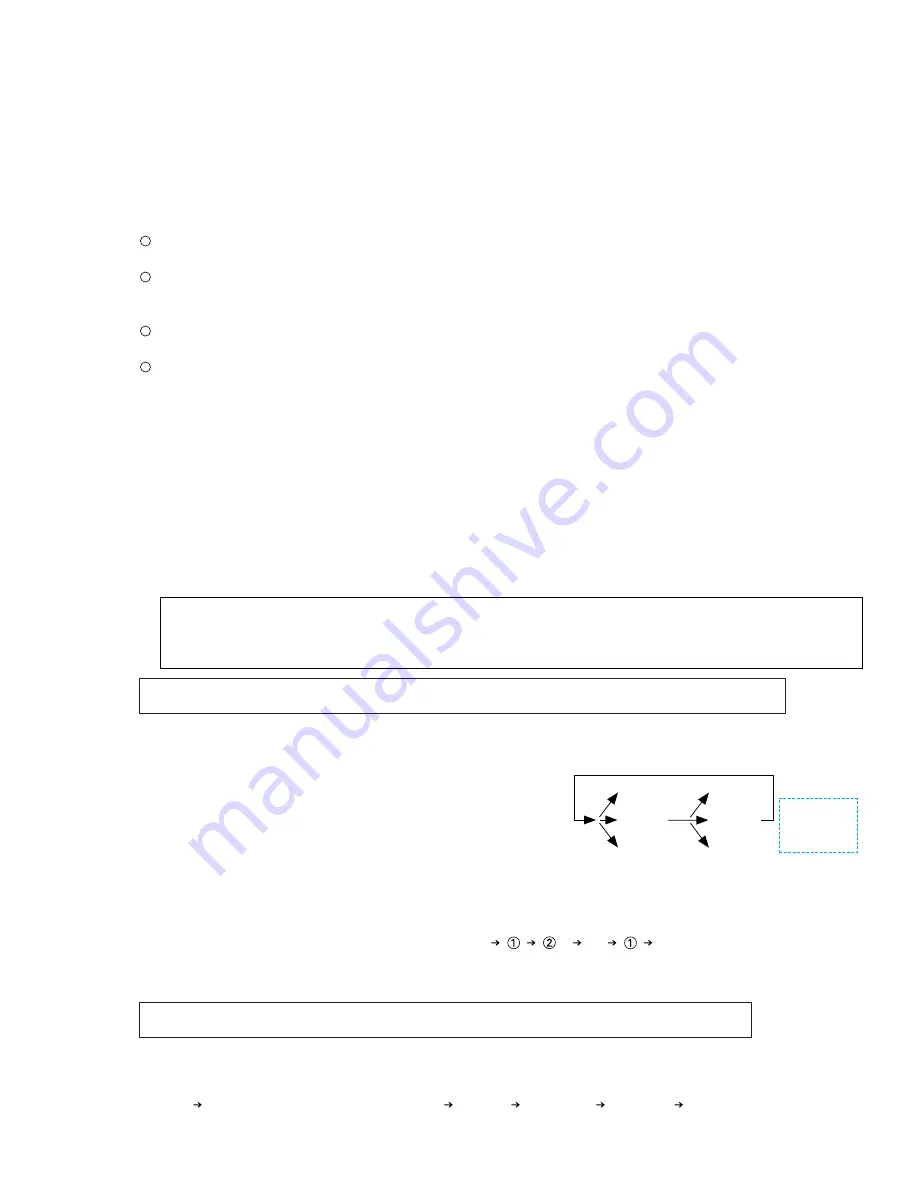
The panel is divided into appropriate blocks, the LEDs and names in the blocks are lit up sequentially, and if there are any faders,
they are driven up and down. Also, panel boards that are divided into multiple boards can also be checked separately.
During diagnostics mode, press any one switch.················ Acceleration
During diagnostics mode, press any two switches. ············ Stop
During diagnostics mode, press any three switches. ·········· Deceleration
During diagnostics mode, press any one switch.················Forward
During diagnostics mode, press any two switches. ············Restart
During diagnostics mode, press any three switches. ··········Return
Hold down any two switches for at least
one second to switch to the next block.·······················(When the inspection starts, the entire selected block is lit up for two
seconds.)
All
···
All
(If something other than checking all blocks has been specified, checking
of only the specified blocks is repeated.)
All the LEDs and names on the panel are lit up.
Whenever it pushes arbitrary buttons for 1 second, LED can be made to turn on in the order of the following.
* Switch, fader, and encoder inputs are invalid during this test.
All lit
Switches the outer periphery LED(Orange)
Red only
Yellow only
Green only
Orange only
(1) Mode 1 Automatic lighting check mode (Started by holding down any two switches for at least one second.
This command is accepted at any time during diagnostics mode.)
(2) Mode 2 All lighting check mode (Started by holding down any three switches for at least one second.
This command is accepted at any time during diagnostics mode except during Mode 1.)
* Precautions about the operating procedure shown in the following items.
Since the decision is momentary when pressing both buttons simultaneously, the decision may not be proper. In such cases,
please try several times. Also note that if the buttons are pressed for more than 1 second, it may be recognized as a different
operation and form another combination.
CS1D
114
1: Acceleration
2: Stop
3: Deceleration
2 (1 second): block switching
1: Forward
2: Restart
3: Return
Fader is not
returned even
when "return"
is designated.
Summary of Contents for CS1D
Page 52: ...3NA V411320 Pattern side 2 MTCPU Circuit Board CS1D 47 ...
Page 65: ...3NA V451420 Pattern side 7 PCIF Circuit Board CS1D 59 ...
Page 72: ...3NA V451350 Component side Pattern side 3 PNC1 Circuit Board to MB23 CN102 CS1D 66 ...
Page 83: ...3NA V411180 Pattern side 2 MSCPU Circuit Board CS1D 77 ...
Page 95: ...3NA V433360 Pattern side 0 OSCPU Circuit Board CS1D 89 ...
Page 97: ...3NA V411130 Pattern side 2 PNIS1 Circuit Board CS1D 91 ...
Page 99: ...3NA V411140 Pattern side 3 PNIS2 Circuit Board CS1D 93 ...
Page 101: ...3NA V411120 Pattern side 2 INCPU Circuit Board CS1D 95 ...
Page 103: ...3NA V411100 Pattern side to CNDS1 CN101 102 CNDS CN503 504 2 PNI1 Circuit Board CS1D 97 ...


