background image


16

MY16-C


Owner’s Manual

ENGLISH


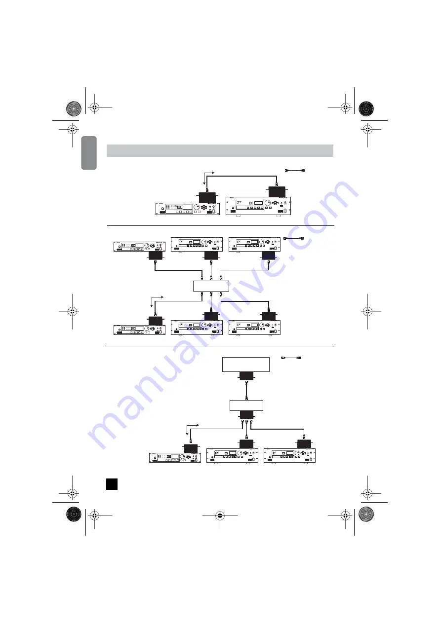
Connecting Two Devices

Connecting via a Hub

Connecting to a Mixer


Connection Examples

DME24N

DME64N

Audio signal and 
control data

MY16-C

MY16-C

Cross Cable

96kHz

88.2kHz

48kHz

44.1kHz

EXT.
CLOCK

MID

MASTER

NETWORK

PEAK

SIGNAL

PEAK

SIGNAL

IN

OUT

SCENE NUMBER

1

2

3

4

5

6

7

8

1

2

3

4

5

6

7

8

Switching Hub

MY16-C

MY16-C

MY16-C

MY16-C

MY16-C

MY16-C

96kHz

88.2kHz

48kHz

44.1kHz

EXT.
CLOCK

MID

MASTER

NETWORK

PEAK

SIGNAL

PEAK

SIGNAL

IN

OUT

SCENE NUMBER

1

2

3

4

5

6

7

8

1

2

3

4

5

6

7

8

96kHz

88.2kHz

48kHz

44.1kHz

EXT.
CLOCK

MID

MASTER

NETWORK

PEAK

SIGNAL

PEAK

SIGNAL

IN

OUT

SCENE NUMBER

1

2

3

4

5

6

7

8

1

2

3

4

5

6

7

8

DME24N 

DME64N

DME64N 

DME24N

DME64N

DME64N

Audio signal and 
control data

Straight Cable

MY16-C

MY16-C

MY16-C

MY16-C

96kHz

88.2kHz

48kHz

44.1kHz

EXT.
CLOCK

MID

MASTER

NETWORK

PEAK

SIGNAL

PEAK

SIGNAL

IN

OUT

SCENE NUMBER

1

2

3

4

5

6

7

8

1

2

3

4

5

6

7

8

Switching Hub

DME24N

DME64N

DME64N

Audio signal and 
control data

Straight Cable

YAMAHA Digital Console

MY16-C


14

MY16-C_E.book Page 16 Tuesday, April 13, 2004 7:32 PM

Summary of Contents for CobraNet MY16-C

Page 1: ...MY16 C Owner s Manual INTERFACE CARD ...

Page 2: ...e the source of interference which can be determined by turning the unit OFF and ON please try to eliminate the problem by using one of the following measures Relocate either this product or the device that is being affected by the interference Utilize power outlets that are on different branch circuit breaker or fuse circuits or install AC line fil ter s In the case of radio or TV interference re...

Page 3: ...ock hazard Turn off all peripheral devices connected to the host device before installation and unplug all related cables CAUTION Always follow the basic precautions listed below to avoid the possibility of physical injury to you or others or damage to the device or other property These precautions include but are not limited to the following Do not touch the metallic leads pins of the circuit boa...

Page 4: ...ata The Peak Audio home page can be viewed on the web at http www peakaudio com In order to take full advantage of the advanced features and performance provided by the MY16 C card we urge you to read this manual thoroughly and keep it in a safe place for further reference Before installing the MY16 C in an audio device please check to make sure that the device is compatible with the MY16 C and ch...

Page 5: ...for more details http www peakaudio com Bundles Audio is transmitted over the CobraNet network in units known as bundles These bundles are processed at the receiving end to reconstitute the original audio signals In the case of the MY16 C a bundle can contain from 3 to 8 channels Each bundle is identified by a number from 0 to 65 279 and audio transmission via the network becomes possible when the...

Page 6: ...ources and it is recommended that the maximum number of bundles be limited to 4 32 channels Unicast bundles should be employed when it is necessary to handle 5 or more bundles at a time Different number ranges are used for multicast and unicast bundles multicast bundles are numbered 1 through 255 while unicast bundles are numbered 256 through 65 279 Digital Audio Data CobraNet Device CobraNet Devi...

Page 7: ...nd received by all conductor and performer devices on the CobraNet network CobraNet Cables and Hubs Category 5 metal cables can be used for runs of up to 100 meters while multimode optical fiber cables can be used for runs of up to 2 kilometers Cross and straight Ethernet cables are available Cross cables should be used for direct connection between two devices Hubs and straight cables are require...

Page 8: ...sable No of Channels The MY16 C System Latency Channels per Bundle 16 bit 48kHz 20 bit 48kHz 24 bit 48kHz 16 bit 96kHz 20 bit 96kHz 24 bit 96kHz 5 33 ms 8 8 7 4 1 4 1 3 1 2 66 ms 8 8 8 4 1 4 1 4 1 1 33 ms 8 8 8 4 1 4 1 4 1 Channels per Bundle Usable No of Channels Bundle1 Bundle2 8 1 8 9 16 7 1 7 9 15 4 1 3 5 7 9 11 13 15 3 1 3 5 9 11 13 MY16 C CobraNet Connector1 CobraNet cable CobraNet audio sig...

Page 9: ...or If an error occurs on the connected network the appropriate indicator will light or flash red If an indicator lights or flashes red try disconnecting it from the corresponding Ethernet connector The indicator will go out if a cable hub or other device connected to the network has failed If the indicator remains lit or flashing even after the cable is disconnected there may be a fault in the MY1...

Page 10: ...See Bundle Number Setting Procedure on page 15 for details Circuit board Switches 7 SERIAL ASSIGNMENT RX Rotary Switch Sets the receive channel for the CobraNet serial control signal from channel 1 through channel 15 The control signals are received from a device that has been set to the matching transmit channel number No serial control reception occurs if this switch is set to 0 8 SERIAL ASSIGNM...

Page 11: ...hes OFF Audio Bits BIT DIP switch 1 sets the audio bit depth Clock Frequency Fs DIP switch 2 sets the audio clock frequency or sample rate n Set all other MY16 C cards installed in the same device to the same clock frequency Set all CobraNet devices receiving and transmitting the same audio signals to the same clock frequency BIT Audio Bit Depth OFF 20 bit ON 24 bit Fs Clock Frequency OFF 48 kHz O...

Page 12: ...switches 5 and 6 CLOCK 1 and CLOCK 2 specify the clock synchronization mode to be used See Clock Synchronization Modes on page 12 for more information LATENCY 1 LATENCY 2 LATENCY OFF OFF 5 33 ms OFF ON 2 67 ms ON OFF 1 33 ms ON ON Reserved CLOCK 1 CLOCK 2 Clock Synchronization Mode OFF OFF Network synchronization OFF ON Host synchronization 1 ON OFF Host synchronization 2 ON ON Reserved 9 MY16 C_E...

Page 13: ... that clock signal is then supplied to the network When the host Synchronization 1 mode is selected make sure that the host device is set to feed a clock signal to the MY16 C card n When using the Host Synchronization 1 mode make sure that the frequency of the clock signal supplied to the MY16 C is within 50 ppm of 48 kHz or 96 kHz Proper operation is not guaranteed with clock frequencies outside ...

Page 14: ...led MY16 C cards to Network Synchronization and the other card s in the same device to Host Synchronization 2 N H1 H1 MY16 C MY16 C MY16 C H1 H1 N Network Synchronization H1 Host Synchronization 1 Network DME64N 24N PM5D etc DME64N 24N PM5D etc DME64N 24N PM5D etc Clock Non network Device b N N H2 H2 MY16 C MY16 C MY16 C N Network Synchronization H2 Host Synchronization 2 Network PM5D etc DME64N 2...

Page 15: ... Host Synchronization 1 H2 Host Synchronization 2 Network DME64N 24N PM5D etc DME64N 24N PM5D etc DME64N 24N PM5D etc Clock Non network Device a N Network Synchronization H1 Host Synchronization 1 H2 Host Synchronization 2 H1 H1 H1 H1 H1 H1 H1 H1 H2 H2 N MY16 C MY16 C MY16 C Network DME64N 24N PM5D etc DME64N 24N PM5D etc DME64N 24N PM5D etc Clock Non network Device b 12 MY16 C_E book Page 14 Tues...

Page 16: ... the number while the right switch sets the least significant bits In short the value of the left switch multiplied by 16 is added to the value of the right switch to produce 256 different values The relationship between the switch settings and bundle numbers is shown in the chart below For example if the left switch is set to 0 and the right switch is set to A the corresponding bundle number woul...

Page 17: ...NETWORK PEAK SIGNAL PEAK SIGNAL IN OUT SCENE NUMBER 1 2 3 4 5 6 7 8 1 2 3 4 5 6 7 8 96kHz 88 2kHz 48kHz 44 1kHz EXT CLOCK MID MASTER NETWORK PEAK SIGNAL PEAK SIGNAL IN OUT SCENE NUMBER 1 2 3 4 5 6 7 8 1 2 3 4 5 6 7 8 DME24N DME64N DME64N DME24N DME64N DME64N Audio signal and control data Straight Cable MY16 C MY16 C MY16 C MY16 C 96kHz 88 2kHz 48kHz 44 1kHz EXT CLOCK MID MASTER NETWORK PEAK SIGNAL...

Page 18: ... HUB AND BRIDGE LINK CONDUCT LOCK ERROR 96kHz 88 2kHz 48kHz 44 1kHz EXT CLOCK MID MASTER NETWORK PEAK SIGNAL PEAK SIGNAL IN OUT SCENE NUMBER 1 2 3 4 5 6 7 8 1 2 3 4 5 6 7 8 Switching Hub DME24N Audio signal and control data Audio signal only Audio signal and control data Audio signal only Straight Cable DME64N MY16 C MY16 C MY16 C MY16 C Straight Cable Primary CobraNet Straight Cable Secondary Cob...

Page 19: ...yp Max Sampling Frequency Range 47 9976 48 48 0024 Terminal Format Latency Data Length Audio Connector CobraNet Primary Secondary CobraNet 5 33ms 20bit 8ch Input 8ch Output RJ45 24bit 6ch Input 6ch Output 2 67ms 20bit 8ch Input 8ch Output 24bit 8ch Input 8ch Output 1 33ms 20bit 8ch Input 8ch Output 24bit 8ch Input 8ch Output Min Typ Max Sampling Frequency Range 95 9952 96 96 0048 Dimensions mm 120...

Page 20: ...ler in Verbindung Les caractéristiques techniques et les descriptions du mode d emploi ne sont données que pour information Yamaha Corp se réserve le droit de changer ou modifier les produits et leurs caractéristiques techniques à tout moment sans aucun avis Du fait que les caractéristiques techniques les équipements et les options peuvent différer d un pays à l autre adressez vous au distributeur...

Page 21: ...AN Yamaha Manual Library http www2 yamaha co jp manual english This document is printed on chlorine free ECF paper with soy ink Auf Umweltpapier mit Sojatinte gedruckt Ce document a été imprimé sur du papier non blanchi au chlore avec de l encre d huile de soja Este documento se ha impreso en papel sin cloro alguno con tinta de soja ...

Reviews: