background image

CDX-E400

6

CDX-E400

 DISASSEMBLY PROCEDURES 

(Remove parts in disassembly order as numbered.)

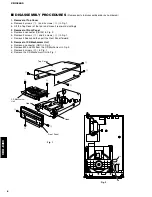
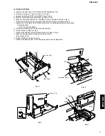
1. Removal of Top Cover

a. Remove 4 screws ( 

q


) and 4 screws ( 

w


) in Fig. 1.

b. Lift the Top Cover at the rear and move it rear-ward slantingly.

2. Removal of Front Panel

a. Remove a connector (CB102) in Fig. 2.
b. Remove 2 screws ( 

e

 ) and 2 screws ( 

r


) in Fig. 1.

c. Remove 2 hooks and then pull the Front Panel forward.

3. Removal of CD Mechanism Unit

a. Remove a connector (CB1) in Fig. 2.
b. Remove W2 and W3 from the CD Mechanism in Fig. 2.
c. Remove 4 screws ( 

t

 ) in Fig. 1.

d. Remove the CD Mechanism Unit in Fig. 1.

Fig. 2

Fig. 1

e

e

q

q

w

r

Top Cover

CD Mechanism

Unit

Front Panel

w

t

t

W2

W3

CB1

CB102

Hook

Hook

Summary of Contents for CDX-E400

Page 1: ... YAMAHA are continually striving to improve YAMAHA products Modifications are therefore inevitable and specifications are subject to change without notice or obligation to retrofit Should any discrepancy appear to exist please contact the distributor s Service Division WARNING Static discharges can destroy expensive components Discharge any static electricity your body may have accumu lated by gro...

Page 2: ...ODUCT SHOULD NOT BE ADJUSTED OR REPAIRED BY ANYONE EXCEPT PROPERLY QUALIFIED SERVICE PERSONNEL WARNING Laser Safety This product contains a laser beam component This component may emit invisible as well as visible radiation which may cause eye damage To protect your eyes and skin from laser radiation the following precautions must be used during servicing of the unit 1 When testing and or repairin...

Page 3: ...0 mm from the objective lens surface on the Optical Pick up Block When checking the laser diode emission keep your eyes more than 30 cm away from the objective lens VARO AVATTAESSA JA SUOJALUKITUS OHITETTAESSA OLET ALTTIINA NÄKYMÄTTÖMÄLLE LASER SÄTEILYLLE ÄLÄ KATSO SÄTEESEEN VARNING OSYNLIG LASERSTRÅLNING NÄR DENNA DEL ÄR ÖPPNAD OCH SPÄRREN ÄR URKOPPLAD BETRAKTA EJ STRÅLEN Optical Pick up ...

Page 4: ...ed 2 Human body grounding Use an anti static wrist strap to discharge the static electricity from your body 2 Handling of the optical pickup Do not use a tester to check the laser diode in the optical pickup The power supply in the tester will damage the laser diode 3 Handling Precautions for the CD mechanism Unit Optical Pickup 1 Handle the CD mechanism unit optical pickup gently as it is an extr...

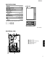
Page 5: ...110 120 220 240V AC 50 60Hz Power Consumption 10W Dimensions W x H x D 217 x 108 x 346mm 8 9 16 x 4 1 4 x 13 5 8 Weight 3 0kg 6 lbs 9 oz Finish Gold color R G models Silver color G B models Specifications are subject to change without notice B British model G European model R General model q MAIN 3 P C B w MAIN 4 P C B R model only e MAIN 1 P C B r CD MECHANISM UNIT t MAIN 2 P C B INTERNAL VIEW 21...

Page 6: ...l of Front Panel a Remove a connector CB102 in Fig 2 b Remove 2 screws e and 2 screws r in Fig 1 c Remove 2 hooks and then pull the Front Panel forward 3 Removal of CD Mechanism Unit a Remove a connector CB1 in Fig 2 b Remove W2 and W3 from the CD Mechanism in Fig 2 c Remove 4 screws t in Fig 1 d Remove the CD Mechanism Unit in Fig 1 Fig 2 Fig 1 e e q q w r Top Cover CD Mechanism Unit Front Panel ...

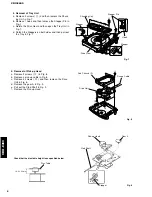
Page 7: ... chassis as shown in Fig 4 f Replace the PU cable of the CD Mechanism with the below specified extension cable Extension cable 16P 230 mm V3340500 g Install the CD Mechanism to the frame mechanism h Connect CB1 as shown in Fig 5 i Connect W2 and W3 to the CD Mechanism as shown in Fig 6 j Place the front panel on the base as shown in Fig 6 Base height 10cm k Connect CB102 as shown in Fig 6 l Connec...

Page 8: ...ws o in Fig 8 b Remove a pick up cable in Fig 8 c Remove 4 screws 0 and then remove the Drive Unit in Fig 8 d Remove the gear A in Fig 9 e Pull out the Sled Shaft in Fig 9 f Remove the Pick up Head 4 Removal of Tray Unit a Remove 2 screws i and then remove the Chuck ing Unit in Fig 7 b Remove 1 hook and then remove the Stopper Pin in Fig 7 c Rotate the Drive Gear and then open the Tray Unit in Fig...

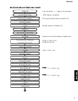
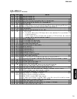
Page 9: ... scan Focus gain rough ADJ Focus search operation Focus lock servo ON Spindle motor accelerated Tracking servo ON Spindle servo ON Feed servo ON OPEN appears in the indicator TRV signal is output until detection of LIMIT switch Stop after detection of LOADING switch Proceeds to next step after detection of LOADING switch if FLSW L IC103 21 pin Proceeds To Next Step LSON L IC101 2 pin FLOCK H L IC1...

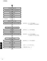
Page 10: ...ator Tracking balance ADJ only tray OPEN CLOSE Focus balance ADJ Focus gain ADJ Tracking gain ADJ TOC READ TRACK NO 1 is searched Set to SEARCH by means of Y T key After searching the beginning MUTE is cancelled PLAY Press the STOP key Laser OFF Forced feed return STOP MUTE ON L H Q7 Collector MUTE ON L H Q7 Collector FLSW IC103 21 pin L MUTE OFF H L Q7 Collector 0 00 appears in the time indicator...

Page 11: ... Op Cl AutoAdj 1 AutoAdj 2 AutoAdj 3 TV Rev TV Fwd TV Stop SP Accel SP Brake SP SV On SP SV Off SP Stop FO Search TR TV Off 1Kick Rev 1Kick Fwd 10 K Rev 10 K Fwd 30 K Rev 30 K Fwd FUNCTION Tray open close Auto adjustment mode 1 TR off set FO off set FO rough gain adjustment Auto adjustment mode 2 TR balance TR rough gain adjustment Auto adjustment mode 3 FO fine gain TR fine gain FO balance adjust...

Page 12: ...p Reverse 30 tracks kick continuously Coefficient set up mode upper digit down Forward 30 tracks kick continuously Coefficient set up mode upper digit up Reverse 150 tracks kick continuously Coefficient set up mode lower digit down Change the coefficient mode Conefficient set up mode Return to product mode with set up coefficient Test mode function List of Remote Controller keys Note Check FL disp...

Page 13: ... MN35511 does not give response of SENSE with resetting by the unit s microcomputer Error Messages List No for each state meaning of X PLAY X 0 SCAN X 2 PAUSE X 3 PEAK SEARCH X 4 SEARCH X 5 START X 7 STOP X 8 LOADING X 9 OPEN X NO DISC X C 1 Error Code Troubleshooting Error code X0 X1 73 Data cannot be read Error codes 94 95 Poor tray loading operation Motor defective Control IC IC302 defective Mi...

Page 14: ...ng play but time display advances properly FOCUS servo system defective YES Is FOCUS lock done IC101 or IC102 defective Microcomputer defective YES NO Feed limit switch defective Does tray load properly NO YES Is pick up at innermost position NO Poor tray loading Jitter defective YES Is EFMI signal normal NO Spindle servo system defective YES Does spindle motor run NO c Operates as if no disc load...

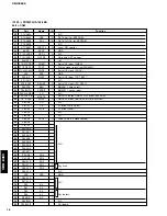
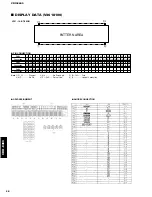
Page 15: ... 8 9 10 11 12 13 14 15 16 17 18 19 20 21 22 23 24 25 26 27 Function Opened state of tray sensing switch input Opened state at L Closed state of tray sensing switch input Closed state at L N C Sound output at H and sound output muted at L Hardware reset output of MN35511 Reset at L Mute output to MN35511 Muted at H Tracking servo drawing signal input from MN35511 Drawn at L Focus servo drawing sign...

Page 16: ...3 44 45 46 47 48 49 50 51 52 53 54 55 56 57 58 59 60 61 62 63 64 65 66 67 68 69 70 71 72 73 74 75 76 77 78 79 80 Port P13 ANI3 P14 ANI4 P15 ANI5 P16 ANI6 P17 ANI7 AVSS P130 ANO0 P131 ANO1 AVREF1 P70 S12 RXD P71 SO2 TXD P72 SCK2 ASCK VSS P20 SI1 P21 SO1 P22 SCK1 P23 STB P24 BUSY P25 SI0 SB0 P26 SO0 SB1 P27 SCK0 P80 A0 P81 A1 P82 A2 P83 A3 P84 A4 P85 A5 P86 A6 P87 A7 P40 AD0 P41 AD1 P42 AD2 P43AD3 P...

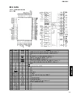
Page 17: ...N DEINTERLEAVE CLV SERVO DIGITAL AUDIO INTERFACE INTER POLATION SOFT MUTING DIGITAL ATTENUATION PEAK DETECT AUTO CUE DSL PLL VCO 16k SRAM PEM L PEM R DD type DAC PLL VCO 2 8 TIMES OVER SAMPLING DIGITAL FILTER DIGITAL DE EMPHASIS SUBCODE BUFFER INPUT PORT SERVO TIMING GENERATOR A D CONVERTER 19 SMCK FCLK 49 VCOF 69 CK384 8 MDATA 7 MCLK 9 MLD 44 ARF 46 DRF 45 IREF 47 DSLF 48 PLLF 52 EFM 53 PCK RESY ...

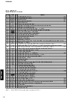
Page 18: ...raverse Feed forced feed output 3 State Traverse Feed drive output Spindle motor ON signal L ON default NC Spindle motor drive signal forced mode output 3 State Spindle motor drive signal servo error signal output Kick pulse output 3 State Tracking drive output Focus drive output Reference voltage for DA output block TVD ECS TRD FOD FBAL TBAL Focus balance adjustment output Tracking balance adjust...

Page 19: ...wer supply terminal for audio DAC Deemphasis detect signal output NC 384fs clock output At the CK384 pin output does not stop while RST L NC Xtal system when command is defaulted Signal processing system when command is switched Mode selecting terminal 5 Test mode setting terminal Normal H 5 Sub code data read clock input Sub code serial output SBCK effective when command is defaulted PACK data us...

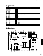
Page 20: ... 11 12 13 14 15 16 17 18 19 20 21 22 23 24 25 26 27 28 29 30 Connection F1 F1 NP 14G 13G 12G 11G 10G 9G 8G 7G 6G 5G 4G 3G 2G NX NX NX NX 1G IC P35 P34 P33 P32 P31 P30 P29 P28 Pin No 31 32 33 34 35 36 37 38 39 40 41 42 43 44 45 46 47 48 49 50 51 52 53 54 55 56 57 58 59 60 Connection P27 P26 NP F2 F2 F2 F2 NP P25 P24 P23 P22 P21 P20 P19 P18 P17 P16 P15 P14 P13 NX NX NX NX P12 P11 P10 P9 P8 Pin No 61...

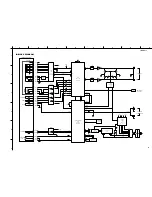
Page 21: ...30 27 2 12 13 9 10 32 31 34 36 2 10 1 18 7 41 15 6 27 39 17 20 1 5 6 7 IC303 M56789FP IC302 LB1641 5M VB 1 OPEN 87 CLOSE 86 2 21 LDRCTL 32 22 21 25 24 27 26 28 29 44 63 64 65 66 LPF IC105 LPF IC3 IC3 IC105 Q3 Q5 Q4 Q6 11 10 15 47 48 5 18 XL102 RESET IN OUT D105 4 MUTE MDATA MCLK 7 8 6 TX MDATA MCLK OUT L OUT R DIGITAL OUT OPTICAL LINE OUT 61 64 47 48 50 51 VB VB 5 5M 5 8 RESET SYSCON T401 L401 20 ...

Page 22: ...IC103 F4 IC104 E3 IC105 C3 IC302 F3 IC303 F2 Semiconductor Location Ref No Location Q1 F2 Q2 F2 Q3 B4 Q4 B4 Q5 B3 Q6 B3 Q7 D3 Q8 C3 Q9 D3 Q10 C3 Q102 E3 Point t EFN V 0 2V div H 0 5µsec div AC 1 1 probe 1 10 MAIN 1 P C B KD0 K2 K0 VP DI CE FL2 KD1 K1 5 GND CL BLK FL1 TO CD MECHANISM UNIT TO CD MECHANISM UNIT LOAD LOAD OPSW DGND CLSW SPDL SPDL FEED FEED FLSW DGND FA TA PD LD F B D 5V TA FA GND GND ...

Page 23: ... RE YE 120V OR YE 220V WH YE 240V BE YE SW501 KD1 K1 5 GND CL BLK FL1 KD0 K2 K0 VP DI CE FL2 MAIN 2 P C B 1 1 6 1 7 3 2 6 4 4 9 4 8 3 3 FROM MAIN 1 3 STANDBY ON WH OR OR R only R only R only R only R only RE WH YE BE YE RE BE FROM POWER CABLE FL2 FL1 AC GND AC TO MAIN 1 W401 L402 7 MAIN 3 P C B MAIN 4 P C B VOLTAGE SELECTOR R only B G only ...

Page 24: ...6 7 8 9 10 11 12 13 14 15 16 49 50 51 52 53 54 55 56 57 58 59 60 61 62 63 64 32 31 30 29 28 27 26 25 24 23 22 21 20 19 18 17 G6 G5 G4 G3 G2 G1 VFL TEST VSS OSCO OSCI VDD RES CE CL DI AM32 AM31 AM30 AM29 AM28 AM27 AM26 AM25 AM24 AM23 AM22 AM21 AM20 AM19 AM18 AM17 AM1 AM2 AM3 AM4 AM5 AM6 AM7 AM8 AM9 AM10 AM11 AM12 AM13 AM14 AM15 AM16 ADDRESS REGISTER SHIFT REGISTER CONTROL BLINKCYCLE REGISTER DISPLA...

Page 25: ...5 1 5 1 0 5 1 0 0 0 0 0 5 0 5 0 0 0 0 0 5 1 5 0 0 0 5 1 0 5 1 5 0 5 1 1 3 5 0 0 12 6 5 0 12 6 0 1 2 5 1 5 5 5 1 28 2 28 8 0 22 6 28 2 32 1 22 1 22 1 12 6 10 2 10 2 5 5 0 0 9 4 9 4 0 10 2 5 2 5 2 5 2 5 2 10 2 0 4 0 5 10 2 5 2 5 2 0 0 AC19 6 AC3 7 2 5 2 5 0 1 1 4 9 5 1 2 6 0 2 3 9 3 9 5 1 2 6 2 6 4 6 2 6 2 6 2 6 2 6 2 6 0 0 0 0 0 2 6 2 6 2 5 2 5 2 5 2 5 2 5 4 1 3 5 2 5 2 5 2 5 2 4 2 7 5 0 2 6 0 2 5 ...

Page 26: ...TTING MODULE LED DSPLY LED DISPLAY LED INFRD LED INFRARED MODUL RF MODULATOR RF PHOT CPL PHOTO COUPLER PHOT INTR PHOTO INTERRUPTER PHOT RFLCT PHOTO REFLECTOR PIN TEST PIN TEST POINT PLST RIVET PLASTIC RIVET R ARRAY RESISTOR ARRAY R CAR CARBON RESISTOR R CAR CHP CHIP RESISTOR R CAR FP FLAME PROOF CARBON RESISTOR R FUS FUSABLE RESISTOR R MTL CHP CHIP METAL FILM RESISTOR R MTL FLM METAL FILM RESISTOR...

Page 27: ...R867470 C EL 47uF 50V C43 UR866470 C EL 4 7uF 50V C44 UR866470 C EL 4 7uF 50V C45 UR867470 C EL 47uF 50V C46 UR866470 C EL 4 7uF 50V C47 UR868100 C EL 100uF 50V C48 Vi716700 C MYLAR 0 01uF 50V C101 VJ599100 C CE TUBLR 0 1uF 50V C102 VJ599100 C CE TUBLR 0 1uF 50V C103 VJ599100 C CE TUBLR 0 1uF 50V C104 V4749000 C EL 150uF 6 3V C105 VG277700 C CE TUBLR 68pF 50V C106 UA653100 C MYLAR 1000pF 50V C107 ...

Page 28: ...0610 FER BEAD BL02RN1 R62T4 Z L401 VU984000 FLTR IE UU10 5 009 L402 V6660800 FER CORE F5 T19x10x10 PJ1 V7720900 JACK PIN LPR6520 E510M PN1 V3750100 PIN L 50 Q1 iB054430 TR 2SB544 D E F G Q2 VK432900 TR 2SD1915F S T Q3 VK432900 TR 2SD1915F S T Q4 VK432900 TR 2SD1915F S T Q5 VK432900 TR 2SD1915F S T Q6 VK432900 TR 2SD1915F S T Q7 iA093320 TR 2SA933S Q R Q8 VS883300 TR 2SB1565 E F Q9 VR510800 TR 2SD2...

Page 29: ...400 30 EXPLODED VIEW R model 101 150 122 150 142 142 152 11 12 103 103 146 145 144 120 142 148 148 149 149 110 110 121 140 140 143 106 15 151 1 104 1 102 1 111 1 110 1 103 1 101 1 111 1 11 1 103 1 110 143 5 2 2 2 1 2 3 2 4 142 142 ...

Page 30: ... 2 V9356300 P C B ASS Y GD MAIN GB 5 VZ573200 CD MECHANISM UNIT KSL 2130CCM Z 11 VZ542500 POWER CABLE 2m R Z 11 V9293600 POWER CABLE 2m G Z 11 VV437300 POWER CABLE 2m B 12 V2438700 CORD STOPPER 10P1 15 V8835000 SUMI CARD C C 16P 100mm P 1 00 101 V7127300 TOP COVER SI 101 V7127400 TOP COVER GD 103 V8783000 REAR PANEL R 103 V8783200 REAR PANEL G 103 V8783100 REAR PANEL B 106 V8782700 LID CD SI 106 V...

Page 31: ...he stopper is not supplied with the tray as a spare part When replacing the tray keep the removed stopper and reuse it Should it be lost and a new one be necessary order service part 8 Main Chassis S and remove the stopper only from it and use it as a spare part Stopper ...

Page 32: ...650 SUB CHASSIS ASS Y S 264628801 12 AX624640 COIL SPRING F 264723601 13 AX624630 COIL SPRING R 262723501 14 AX624660 WASHER 2130 264628901 15 EX604270 P TITE SCREW 2 6x10 768513511 16 AX624620 INSULATOR 262723401 18 AX619160 MAIN CHASSIS S OUTSERT 262555206 19 VH554700 BW HEAD P TITE SCREW 2 6x16 331950151 20 CX675270 DRIVE GEAR S 262554701 21 CX675260 CONTROL CAM S 262554504 22 KX604780 LEAF SWI...

Page 33: ...OR GEAR ASS Y X26257691 3 AX623980 SLED SHAFT 262690801 4 CX679720 GEAR A S 262690701 5 EA020036 PAN HEAD SCREW 2x3 ZMC2 Y 762125515 6 KX604660 LEAF SWITCH 157208511 7 NX613040 PWB MOTOR MOTOR 6P 163967812 8 LX610120 CONNECTOR PIN 6P 156472211 9 CX680030 GEAR 262700301 10 NX636020 OPTICAL HEAD KSM213C Note The parts marked with an asterisk are not available separately Cover ...

Page 34: ...5 4100 HF85 4150 HF45 4220 HF85 4270 HF45 4330 HF85 4390 HF45 4470 HF45 4560 HF45 4680 HF45 4750 HF45 4820 HF45 4910 HF45 5100 HF85 5110 HF45 5120 HF45 5150 HF45 5180 HF45 5200 HF45 5220 HF45 5270 HF45 5330 HF45 5390 HF45 5430 HF45 5470 HF45 5510 HF45 5560 HF45 5680 HF45 5820 HF45 5910 HF45 6100 HF45 6120 HF45 6150 HF45 6180 HF85 6200 HF45 6220 HF85 6240 HF45 6270 HF45 6300 HF45 6330 HF85 6360 HF4...

Page 35: ...CDX E400 CDX E400 ...
Reviews: