background image

ii 

En

Yamaha and the Electronic Industries Association’s Consumer Electronics Group want you to get the 
most out of your equipment by playing it at a safe level. One that lets the sound come through loud 
and clear without annoying blaring or distortion – and, most importantly, without affecting your 
sensitive hearing. Since hearing damage from loud sounds is often undetectable until it is too late, 
Yamaha and the Electronic Industries Association’s Consumer Electronics Group recommend you to 
avoid prolonged exposure from excessive volume levels.

FCC INFORMATION (for US customers)

1

IMPORTANT NOTICE: DO NOT MODIFY THIS 
UNIT!

This product, when installed as indicated in the 
instructions contained in this manual, meets FCC 
requirements. Modifications not expressly approved by 
Yamaha may void your authority, granted by the FCC, 
to use the product.

2

IMPORTANT:

 When connecting this product to 

accessories and/or another product use only high 
quality shielded cables. Cable/s supplied with this 
product MUST be used. Follow all installation 
instructions. Failure to follow instructions could void 
your FCC authorization to use this product in the USA.

3

NOTE:

 This product has been tested and found to 

comply with the requirements listed in FCC 
Regulations, Part 15 for Class “B” digital devices. 
Compliance with these requirements provides a 
reasonable level of assurance that your use of this 
product in a residential environment will not result in 
harmful interference with other electronic devices. 
This equipment generates/uses radio frequencies and, 
if not installed and used according to the instructions 
found in the users manual, may cause interference 
harmful to the operation of other electronic devices.

4

Compliance with FCC regulations does not guarantee 
that interference will not occur in all installations. If 
this product is found to be the source of interference, 
which can be determined by turning the unit “OFF” 
and “ON”, please try to eliminate the problem by using 
one of the following measures:

5

Relocate either this product or the device that is being 
affected by the interference.

6

Utilize power outlets that are on different branch 
(circuit breaker or fuse) circuits or install AC line 
filter/s.

7

In the case of radio or TV interference, relocate/
reorient the antenna. If the antenna lead-in is 300 ohm 
ribbon lead, change the lead-in to coaxial type cable.

8

If these corrective measures do not produce 
satisfactory results, please contact the local retailer 
authorized to distribute this type of product. If you can 
not locate the appropriate retailer, please contact 
Yamaha Electronics Corp., U.S.A. 6660 Orangethorpe 
Ave., Buena Park, CA 90620.

9

The above statements apply ONLY to those products 
distributed by Yamaha Corporation of America or its 
subsidiaries.

We Want You Listening For A Lifetime

Summary of Contents for ATS-1010

Page 1: ...U Front Surround System ATS 1010 OWNER S MANUAL ...

Page 2: ...s or when unused for long periods of time 14 Refer all servicing to qualified service personnel Servicing is required when the apparatus has been damaged in any way such as power supply cord or plug is damaged liquid has been spilled or objects have fallen into the apparatus the apparatus has been exposed to rain or moisture does not operate normally or has been dropped IMPORTANT SAFETY INSTRUCTIO...

Page 3: ...h these requirements provides a reasonable level of assurance that your use of this product in a residential environment will not result in harmful interference with other electronic devices This equipment generates uses radio frequencies and if not installed and used according to the instructions found in the users manual may cause interference harmful to the operation of other electronic devices...

Page 4: ...unit with chemical solvents this might damage the finish Use a clean dry cloth 12 Only voltage specified on this unit must be used Using this unit with a higher voltage than specified is dangerous and may cause fire damage to this unit and or personal injury Yamaha will not be held responsible for any damage resulting from use of this unit with a voltage other than specified 13 To prevent damage b...

Page 5: ...es grow old the effective operation range of the remote control decreases considerably If this happens replace the batteries with two new ones as soon as possible Do not use old batteries together with new ones Do not use different types of batteries such as alkaline and manganese batteries together Read the packaging carefully as these different types of batteries may have the same shape and colo...

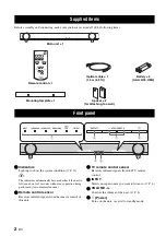
Page 6: ... 2 Remote control sensor Receives infrared signals from the remote control of this unit 3 TV remote control sensor Receives infrared signals from the TV remote control 4 INPUT Selects an input source you want to listen to P 6 5 VOLUME Controls the volume of the unit P 8 6 Power Turns on the unit or sets it to standby mode Supplied items Front panel Remote control 1 Battery 2 AAA R03 UM4 Spacer 2 f...

Page 7: ...ially available screws and the supplied spacers at the marks 3 Hang the unit on the screws using the brackets on the rear of the unit Do not attach the unit to a wall that is made of weak materials such as plaster or veneered woods Doing so may cause the unit to fall Use commercially available screws that can support the weight of the installation Make sure you use specified screws to attach the u...

Page 8: ...eakers to off Connection Connecting a TV The unit plays the audio output from your TV Connect input components such as a BD player etc to your TV first and check the components play properly before connecting to the unit See the manuals of your TV and BD player etc for details After that connect the unit to your TV as the illustration below Setting your TV OPTICAL OUTPUT SYSTEM CONNECTOR SUBWOOFER...

Page 9: ...D player STB etc to the unit directly in the following cases When the unit does not play the sound output from the components connected to your TV P 4 When your TV does not have any audio input jacks to connect input components such as a BD player etc SYSTEM CONNECTOR SUBWOOFER OUT SYSTEM CONNECTOR MONAURAL INPUT OPTICAL OUTPUT COAXIAL OUTPUT SYSTEM CONNECTOR SUBWOOFER OUT System connector cable c...

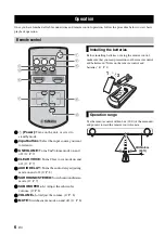
Page 10: ...elay adjusting mode on and off P 8 6 SURROUND STEREO Switch surround stereo mode P 7 7 SUBWOOFER Adjust the subwoofer volume P 8 8 VOLUME Adjust the volume P 8 9 MUTE Switches mute mode on and off P 8 Before installing batteries or using the remote control make sure that you read precautions on the remote control and batteries in Notes on the remote control and batteries P 1 Use the remote control...

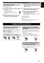
Page 11: ...refer to the instruction manual for the product Playback in surround sound You can enjoy a realistic sound effect using Yamaha s exclusive AIR SURROUND XTREME Playback in stereo sound An extended sound is achieved for a 2 channel source While watching the TV compensate the excessive volume differences to make it easier to hear during the following cases When switching the channel When a TV program...

Page 12: ...y and red a longer delay 3 Press AUDIO DELAY to exit the adjustment mode y The adjustment mode is canceled if the unit is left for 20 seconds without any operation being performed Although the unit has a subwoofer built in you can use commercially available powered subwoofer of your choice Refer to Alternative connections P 5 1 Set the unit to standby mode 2 Press both the VOLUME button and button...

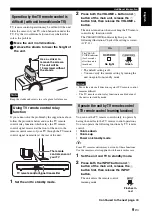
Page 13: ...ify the current setting by turning the unit on again from standby mode Move the unit in all directions again if TV remote control remains difficult The TV remote control relay function is enabled even if the unit is in standby mode You can use the TV remote control solely to operate by having the unit learn the TV remote control operations You can operate the following functions by TV remote contr...

Page 14: ...disturb TV remote control learning 1 Set the unit to standby mode 2 Press both the INPUT button and button of the main unit release the button first then release the INPUT button 3 Press the INPUT button of the main unit again for more than 3 seconds 4 Release the INPUT button of the main unit when qD DTS indicator flashes Press the button of the main unit for more than 3 seconds to finish the rem...

Page 15: ...ation immediately after turning on the unit Playback of the subwoofer P 8 TV remote control relay function P 9 Indicators Built in subwoofer Off External subwoofer Off Built in subwoofer On External subwoofer On Indication of the setting mode Setting mode Indicators Audio delay control P 8 TV remote control learning P 9 Normal indication INPUT TV BD DVD STB Stand by SURROUND Surround playback Ster...

Page 16: ...y back the source in surround effect 7 No bass The external subwoofer makes no sound The volume of the subwoofer channel may be set to minimum level Adjust the volume level of the subwoofer 8 Opposite setting of subwoofer is selected Select collect setting of subwoofer 8 The source does not contain low frequency signals The cable between the unit and the subwoofer not connected when selecting play...

Page 17: ...your TV is opposite from the beginning Press the power button of TV remote control to set your TV and the unit to standby mode after pressing the power button of your TV itself and of the unit to set both your TV and the unit to on 9 The TV remote control is out of work even if you use TV remote control relay function The unit and TV are too close far from one another Try to use the TV remote cont...

Page 18: ... Jacks Optical 2 TV BD DVD Coaxial 1 STB Output Jacks Subwoofer 1 System Connector for subwoofer power interlock 1 General Power Supply AC 120 V 60 Hz Power Consumption 22 W Standby Power Consumption Less than 0 5 W Dimensions W H D With stands 890 107 120 5 mm 35 1 8 4 1 4 4 3 4 in Weight 4 2 kg 9 3 lbs Specifications are subject to change without notice This system employs new technologies and a...

Page 19: ......

Page 20: ... 2011 Yamaha Corporation Printed in Malaysia ZA81330 ...

Reviews: