TEST PROGRAM
AO8
22
A. Preparations for Inspection
• Writing the firmware
This equipment requires firmware. When there are changes to the manufacturing processes and program for this equipment, it is
necessary to download the new firmware to FlashRom from a PC. (If there is no firmware loaded or its checksum does not match
the correct value, when the power is first switched on the LED on UNC flashes at one second intervals.)
The only sheet for which the firmware must be downloaded is UNC. There are two methods for writing this firmware: to write it
indirectly using the CS1D or DSP1D RS232C port or to write it directly to the AO8 UNC sheet. The detailed methods are given
below.
• Method for writing firmware using the DSP1D RS232C port
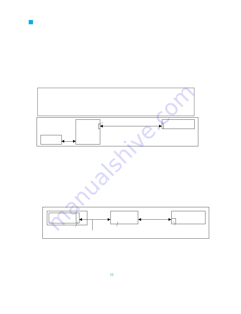
* It is possible to write the AO8 (UNC) firmware from the PC via the CS1D or DSP1D RS232C port. This is the method
normally used.
1. Install and set the above reference destination files.
2. At the very least, connect as shown in the figure above (when A08). If it is not possible to avoid making signal connections
other than these, turn off the power supply for all components other than those relevant to the write object and turn off the
control power supply for the volume of other components such as speakers and amplifiers. Please note that at that time, if other
AI8/A08 are connected they may be written and because of this, there is no guaranteed that the writing has been properly
performed even if the writing shows a successful completion.
3. Use the methods shown in the CS1D Test Program Specifications to write the firmware to the necessary units.
After the
firmware has been written, check that the versions for all the units are the desired versions.
• Method for writing firmware directly to the AO8 UNC
* When there is some kind of problem or the DSP1D is unavailable due to this equipment's production processes and
the firmware can not be written with the method on the previous page, use the method below.
1. Connect the D-sub 9-pin serial cables (cross) and DSP-CHECK board between the 5-pin connector for the target board and the
PC. At this time, do not connect other signal lines.
2. After PM1DLOAD starts up, select CardDirect with MODE SELECT, then press OK.
3. Use the setup menu to properly set the serial port to be used and then select AI8/A08 from the pull-down menu.
4. Check on the items for OUTPUT 1 on the list and click the write button.
5. After writing ends, end PM1DLOAD.
6. Switch off the power for AO8 and remove the PH connector, then switch the power for AO8. DSP1D on again and check that it
starts up normally. (Operation is normal if an "
" is displayed in 7-segment display for A08.)
• PM1D inspection PC software preparation
Inspection with this device uses special PC software for inspection.
The software versions are as follows
Software used:
PM1DLOAD within PM1D system software
Firmware used:
AI8/AO8 firmware in PM1D system software
Version used:
PM1DLOAD and the AI8/AO8 firmware are files composed using a PM1D SYSTEM SOFTWARE
with a version later than the version shown on the cover.
(Managed with the already drawn CD-R assembly drawing (3JL-XY714A0).)
* For the installation and setting methods, refer to the CS1D Test Program Specifications.
Connect the 5-pin PH connectors
with a straight-wired cable.
For the connection diagram, refer to the
LMY-slot inspection jig specifications.
Only COM1 can be used.
AO8
UNC sheet
Serial
communications jig
Serial connection
D-sub 9-pin cross-cable
PC
(Windows 95 or later)
1 2 3 4 5 6 7 8
Serial connection
D-sub 9-pin
cross-cable
RS232C
DSP1D
INPUT A
AO8
One or the other
OUTPUT 1
PC
(Windows 95 or later)


