background image


3.9  Connecting the ground wire   


WARNING 

-  Make ground connection when working with flammable material or in explosive atmosphere. Rapid 

pumping of material can result in static electrical charge. Also, be sure to provide proper ventilation 
where a flammable atmosphere may exist. 

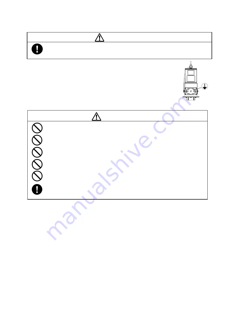
1)  When installing the pump, be sure to connect the ground wire at the 

specified position. (Fig. 8)   

2)  Also connect ground wires to peripheral equipment and piping. 
3) Use 

2.0mm

2

 minimum ground wire. 


4. Operating Method 

CAUTION 

Keep your face away from the bleeder valve. Material may spurt out together with compressed air. 
 

Do not exceed the maximum operating pressure of the pump (0.7MPa). Overpressure may cause a 
product failure resulting in serious personal injury and/or property damage. 

Keep your hand away from the three studs connecting the air motor and lower pump. Fingers can 
get caught in the reciprocating plunger. 

Keep your face away from the silencer. Compressed air is exhausted at high pressure, causing 
moisture to freeze leading cause of injuries. 

In case of a pump malfunction or shutdown, refer to “5.2 Troubleshooting” to judge the situation 
thoroughly and disassemble the pump only as necessary. 

Avoid allowing the pump to run dry as much as possible. The life expectancy of packings will be 
reduced. The pump runs dry when a container becomes empty. Stop the pump immediately after 
the material in a container is all gone. 


4.1  Description of valve 

-  Pump Air Regulator (sold separately) 

Function  : Controlling air pressure for pump operation. 
To operate : Clockwise turn will increase pressure. Counterclockwise turn will decrease pressure. 

  (It can be locked by pushing the knob in.) 

Note 

: The maximum allowable operating pressure of the pump is 0.7MPa. DO NOT exceed this limit. 

Remark 

: Discharge pressure can be calculated by multiplying the air pressure by the pump ratio. 


-  Air Valve, Pump (sold separately) 

Function  : Starting/Stopping the pump. 
To operate : When the lever is parallel to the pipe, the valve is open. If the lever is perpendicular to the pipe, 

  the valve is closed. 

Note 

: In case of emergency, close the emergency stop valve attached to the air piping instead of this 
 valve. 


4.2  Solvent cup (125 Type only) 

1

 The pump is equipped with a solvent cup to keep the packing from sticking to the plunger. Shut down the pump 

and then fill the cup 2/3 full with suitable lubricant or solvent. 

2

 When lubricant in the cup runs out during operation, shut down the pump first and refill the cup. 


Fig. 8

 Position for connecting 

the ground wire


Summary of Contents for 40 Series

Page 1: ...SR140P50 P MODEL No 854559 50 1 SR140P25 D MODEL No 854560 25 1 SR140P38 D MODEL No 854561 38 1 SR140P50 D MODEL No 854562 50 1 SR125D13 MODEL No 854664 13 1 WARNING Prior to operating this pump be s...

Page 2: ...ings and Cautions To use this product safely be sure to observe the contents of the following description In this manual warnings and cautions are indicated by using symbols These symbols are intended...

Page 3: ...erty damage Be sure to use the unit in accordance with the specifications described in 7 Specifications in this manual Installation and piping Ground connection Make ground connection to pump and peri...

Page 4: ...or breakage Do not plumb directly Do not connect the material outlet and piping directly Attach a flexible tube like a hose to connect the pump to the piping The pump if connected directly to the pipi...

Page 5: ...Connecting suction piping 4 3 6 Discharge piping 4 3 7 Air piping 4 3 8 Preparation for use 4 3 9 Connecting the ground wire 5 4 Operating Method 4 1 Description of valve 5 4 2 Solvent cup 5 4 3 Filli...

Page 6: ...are loose The nylon tube and the silencer are detached from the pump in the packaging due to the shipping conditions 2 Operating principle Yamada s air powered pumps employ reciprocating motion syste...

Page 7: ...ion Use a stopper caster wheel with a brake or other locking device to prevent a mount from moving due to reciprocating pump vibration Before installing the pump verify that the shovel at the bottom i...

Page 8: ...ng as deeply as possible After the installation please make sure that the nylon tube is firmly connected by lightly pulling it 3 3 Installation of silencer CAUTION Each connection is capped Remove the...

Page 9: ...material outlet 2 Connect the other end of the hose to a delivery pipeline Attach a valve at the connection between the hose and the piping for maintenance and keep it closed until unit installation i...

Page 10: ...e the pump only as necessary Avoid allowing the pump to run dry as much as possible The life expectancy of packings will be reduced The pump runs dry when a container becomes empty Stop the pump immed...

Page 11: ...al from the outlet Once the air in the piping is released completely close the air valve for the pump and set the pump air regulator to 0MPa The pump is now ready for operation 2 Adjust the pump air r...

Page 12: ...ng pump operation and There is no abrasion or deterioration apparently in each part of the pump Lubricate pump Lubricate pump according to the following procedure Close the air valve for the pump and...

Page 13: ...ve is defective wear of seat surface inclusion of foreign material or packings are damaged If downward movement of plunger is faster seat surface of foot valve is defective wear of seat surface inclus...

Page 14: ...804815 716246 Valve seat 1 per unit 10 million cycles Block 1 per unit 10 million cycles Spring 1 per unit 10 million cycles Ball 1 per unit 10 million cycles O ring 1 per unit 5 million cycles O ring...

Page 15: ...nal injury or property damage Pump 10 years Standard Conditions of Use SR140P25 SR140P38 SR140P50 SR125D13 Application Season Temperature Material being pumped Supply air pressure Daily Amount of Mate...

Page 16: ...1 632059 3 Slit pin 5 716288 Joint 1 6 716289 Connecting rod 1 7 716286 716290 Stud 3 8 631918 Wave spring washer 3 9 627045 Nut 3 10 804816 804817 804818 804816 804817 804818 Lower pump assembly 1 1...

Page 17: ...1 2 716409 Bushing 1 3 700350 Cap nut 1 4 632059 Slit pin 3 5 716288 Joint 1 6 716597 Connecting rod 1 7 716290 Stud 3 8 631918 Wave spring washer 3 9 627045 Nut 3 10 804956 Lower pump assembly 1 11 7...

Page 18: ...7 640132 O ring 1 10 38 716309 Foot valve housing 1 10 39 640015 O ring 2 10 40 685617 Pin 1 10 41 640020 O ring 1 10 42 715260 Piston body 1 10 43 685618 U packing 2 10 44 685619 Backup ring 2 10 45...

Page 19: ...t 1 10 37 640132 O ring 1 10 38 716316 Foot valve housing 1 10 39 686305 O ring 2 10 40 632544 632543 Pin 1 10 41 640016 640015 O ring 1 10 42 715568 715576 Piston body 1 10 43 685787 685792 U packing...

Page 20: ...valve housing 1 10 15 640135 O ring 2 10 16 701542 Stopper 1 10 17 713550 Foot valve 1 10 18 701538 Shovel rod 1 10 19 701539 Shovel 1 10 20 631916 Wave spring washer 1 10 21 627012 Nut 1 10 22 83301...

Page 21: ...nd drum pump respectively 3 Measurement method of A weighted sound pressure level is based on ISO 1996 4 Measurement method of A weighted sound power level is based on ISO 3744 0 2 0 7 MPa Rc3 8 Equip...

Page 22: ...NOTE Avoid continuous operation if a desired discharge volume is in the shaded area in the right side of each figure SR140P50 Performance curve SR140P25 Performance curve SR140P38 Performance curve SR...

Page 23: ...cause corrosion inflation or dissolution of the component parts of the product 4 Irregularity arising from repair made by other than by our firm our regional office dealer or authorized service perso...

Page 24: ...8504 Japan PHONE 81 0 3 3777 0241 FAX 81 0 3 3777 0584 E mail intl yamadacorp co jp Web www yamadacorp co jp YAMADA THAILAND CO LTD 41 79 Moo 6 Bangcha long Bangplee Sumutprakarn10540 Thailand PHONE 6...

Reviews: