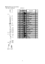
YAMADA 110 Series Instructions Manual Download Page 9


4

Fig. 5 


5. Maintenance and Inspection 

5.1 Troubleshooting and Corrective Measures 

Symptom 

Contents of inspection 

Corrective measure 

 The pump fails to start. 

-  Check if the air regulator is normally operated. 

-  Check if the valve in the course of the pipe is not 

closed. 


(Remove the delivery hose at the pump-side outlet and 

operate the pump.) 

 If the pump is operated, the delivery hose, pipe, or 

outlet valve (gun) is clogged, or the operating 

pressure is low. 

 If the pump is not operated, the pump is defective. 


(Separate the lower pump and operate the pump with 

only the air motor.) 

 If the pump is operated, the lower pump is defective. 

 If the pump is not operated, the air motor is defective. 

 Pressure check. 

(0.15 to 0.7MPa) 


 Inspection 


 Repair service for 

the lower pump 

 Repair service 

 The pump fails to stop. 

-  Check if the pump cannot be stopped when the 

material outlet side remains open. 

-  If the outlet side is closed, check if any leak occurs at 

the pipe, delivery hose, or each connecting portion. 

-  Check if the air bleed valve or bleeder valve remains 

open. 

-  Check if there is no material. 


 Inspection 


Replenishment 

 The pump is operated 

but does not feed the 

material by pressure. 

-  Loosen the air bleed valve to bleed the air staying 

under the inductor plate and tighten the valve again. 

-  If the pump cannot be operated, open the bleeder 

valve. When the material comes out, tighten the valve 

again. 

If the material is not fed, disassemble the check valve 

and clean and check the ball seat surface and spring.

-  The pump cannot be operated yet, the pump is 

defective. 

 Inspection 


 Inspection 


 Disassembly and 

inspection 

 Repair request for 

the lower pump 

 The pump is operated 

but the pressure and 

flow rate are insufficient. 

-  Check if the supply air pressure is insufficient. 

-  Check if the packing of the air valve is not worn away. 

 Pressure check 

 Repair request for 

the lower pump 


5.2 Maintenance and Inspection 
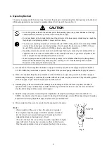
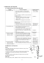
[Oiling] 

For lubrication of the pump, perform oiling with a lubricant once every 10 days. 

Apply the lubricant as follows. 

1)  Remove the air regulator. 

2)  As shown in the Fig. 5 at right, inject drops of lubricant (approximately 0.5mL) 

into the oil cup. Use turbine oil first class ISO (VG-32) as the lubricant. 

[Inspection] 

The packing and parts around slide portion of the pump are worn away. Check 

and replace them once a year. 

[Daily check] 

Before starting pump operation, retighten the bolts or connection parts of the pump. (Fig. 6) 

Fig. 6 

Summary of Contents for 110 Series

Page 1: ...5 MODEL No 851830 DR 110B5 MODEL No 851831 SH 110B5SUS MODEL No 851832 DR 110B5SUS MODEL No 851833 WARNING Prior to operating this pump be sure to read this operation manual for safety After reading the manual please keep it at hand any time for your quick reference INSTRUCTION ...

Page 2: ...manual warnings and cautions are indicated by using symbols These symbols are intended to prevent death or serious injury that may be caused to the operator or those who are around the product and damage that may be caused to the articles that are around the product as well as to use the product safely and correctly Each symbol is indicated and has a meaning as shown below Read the description wit...

Page 3: ... Attach a valve for stop in emergency or regulator to the air supply pipe to keep supply air pressure under 0 7MPa Discontinue it when you feel a hazard or abnormality during the work And correspond according to the troubleshooting Stop pump operation immediately when a drum becomes empty Running the pump dry will cause excessive vibration resulting in reduction of pump life and damage to other eq...

Page 4: ...stalling the pump Back injury may be caused by lifting the pump Do not touch the surfaces of the pump and the hose when pumping high temperature material Risk of burns exists Stop the air supply source after the end of work when not using this pump for a long time such as nighttimes and holidays Also open the valve of the exhalation port and liberate pressure in the pump and the hose There is a po...

Page 5: ...ration 1 3 Installation 3 1 Installing drum type DR pump 2 3 2 Installing stubby type SH pump 2 3 3 Installing delivery hose 2 3 4 Connecting supply air 2 4 Operating Method 3 5 Maintenance and Inspection 5 1 Troubleshooting and Corrective Measures 4 5 2 Maintenance and Inspection 4 6 Disassembly and Assembly 5 7 Parts Disassembly Drawing and Parts List 6 8 Specification 9 9 Limited Warranty 11 ...

Page 6: ...rive the pump and a lower pump to pump up the material as shown in the Fig 1 at right When the compressor feeds compressed air to the air motor the air piston starts up down reciprocating motion by means of the function of the built in air changeover mechanism This function is transmitted to the piston of the lower pump by the connecting rod that connects the air piston of the air motor to the pis...

Page 7: ...ssure ball valve at the end of the piping Fig 3 When using the pump for paint circulation install pressure valve and then connect the return hose to the pump CAUTION Do not connect the piping directly to the pump Vibration caused by direct connection may result in damage to the piping or generation of noise As for a drum type it may also be the cause of difficulty in changing a drum and inconvenie...

Page 8: ...lockwise to supply air into the pump When the supply air pressure reaches 0 15 to 0 2MPa the pump starts to operate The pointer of the pressure gauge indicates the supply air pressure 2 When air is supplied the pump is operated for a while to fill the hose pipe and gun with oil and then stopped automatically If the pump is continuously operated without stop leak may have occurred in any connecting...

Page 9: ... pump is operated but does not feed the material by pressure Loosen the air bleed valve to bleed the air staying under the inductor plate and tighten the valve again If the pump cannot be operated open the bleeder valve When the material comes out tighten the valve again If the material is not fed disassemble the check valve and clean and check the ball seat surface and spring The pump cannot be o...

Page 10: ...t on the vise in any case 5 Loosen the lock nut 6 Pull the lower pump and unscrew the cap nut that connects the connecting rod and plunger rod Then the lower pump can be separated from the air motor Fig 7 Disassembling the lower pump Disassembling the foot valve 7 Grip the knurling part of the suction tube on a vise Set a wrench on the foot valve and unscrew it to remove the suction tube Fig 7 8 R...

Page 11: ...acking can be removed Fig 8 15 Wash and check each part If scratch or wear is found change to new parts 16 To reassemble after checking take opposite procedure of disassembling Disassembling the muffler The silencing effect of the muffler at the exhaust port is halved by clogging caused by long term use Disassemble and inspect it periodically 1 Remove the stop ring with stop ring pliers The muffle...

Page 12: ... Connecting rod 1 7 13 640012 O ring 1 7 14 632774 Spring pin 1 7 15 627016 Nut 1 7 16 701554 Housing 1 7 17 630334 Ball 1 7 18 701553 Valve seat 1 7 19 770233 Revolving stopper 1 7 20 701533 Toothed lock washer 2 7 21 701534 Washer 2 7 22 640131 O ring 1 7 23 701532 Back up washer 1 7 24 770151 L packing 2 7 25 701556 Pin 1 7 26 630341 Ball 1 7 27 640134 O ring 1 7 28 704587 704586 704587 Foot va...

Page 13: ...ube 1 7 12 680177 Spring pin 1 7 13 702290 703815 Connecting rod 1 7 14 628016 Nut 1 7 15 702286 Housing 1 7 16 630434 Ball 1 7 17 770233 Revolving stopper 1 7 18 702280 Valve seat 1 7 19 770501 L packing 2 7 20 770236 Back up washer 1 7 21 702287 Piston body 1 7 22 702288 Foot valve 1 7 23 705336 Pin 1 7 24 630442 Ball 1 7 25 770237 Packing 1 7 26 702289 703816 Foot valve 1 No Part No Description...

Page 14: ...LEVEL 1 A WEIGHTED SOUND POWER LEVEL 2 ENV TEMPERATURE MATERIAL TEMP 14 1 kg 12 0 kg 17 0 kg 15 0 kg 16 0 kg 1 Measurement method of A weighted sound pressure level is based on ISO 1996 2 Measurement method of A weighted sound power level is based on ISO 3744 3 Discharge volume per cycle varies according to use conditions 90 dB 101 dB 0 60 100mL 0 80 60 mm 5 x 1 Rc 3 4 G 1 4 F Union Adapter 0 3 0 ...

Page 15: ...10 Dimension Model No A mm B mm 851829 843 523 851830 861 541 851831 1180 860 851832 857 538 851833 1229 909 851829 851831 851833 851830 851832 Pump mounting hole layout ...

Page 16: ...3 Malfunction arising from use with a fluid that may cause corrosion inflation or dissolution of the component parts of the product 4 Irregularity arising from repair made by other than by our firm our regional office dealer or authorized service personnel 5 Malfunction arising from modification of the product by other than authorized service personnel 6 Wear and tear of parts that must be regular...

Page 17: ...MEMO ...

Page 18: ...ATION INTERNATIONAL DEPARTMENT No 1 3 1 Chome Minami Magome Ohta Ku Tokyo 143 8504 Japan PHONE 81 0 3 3777 0241 FAX 81 0 3 3777 0584 YAMADA EUROPE B V Aquamarijnstraat 50 7554 NS Hengelo o The Netherlands PHONE 31 0 74 2422032 FAX 31 0 74 2421055 ...

Reviews: