11
SINGLE & DOUBLE GIRDER TOP-RUNNING BRIDGES
WITH INDIVIDUAL MOTOR DRIVEN
END TRUCKS
P/N: 11532620 REV. AA
September 2018
Brake Air Gap Inspection for ABM Gearmotors
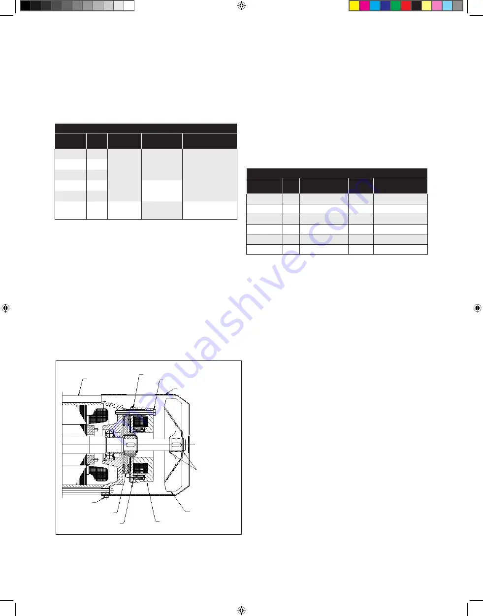
To inspect brake air gap refer to figure 6:
1. Disconnect and lock out power supply
2. Remove brake cover
3. Carefully roll the o-ring back towards the magnet body exposing
the air gap between the armature plate and magnet. Use feeler
gauge and measure the gap between the armature plate and
magnet. If gap exceeds maximum allowed, replace the brake.
4. Roll o-ring back into place and re-install brake cover.
5. Turn power back on to crane and test brakes for proper
operation.
Brake Air Gap Inspection for Nord Gearmotors
The brake air gap is checked by placing a feeler gage between metal
anchor plate and the brake coil housing. This procedure is identical
even for the larger twin rotor brakes.
Procedure
1. Loosen the fixing screws that attach the brake to the motor’s end-
shield by approximately half a turn.
2. If required, the brake assembly may be loosened slightly from the
motor’s end shield by turning the threaded setting bolts (hollow
screws) that surround the fixing screws, counter clockwise, into
the brake coil housing.
3. Depending upon whether or not the air gap needs to be
decreased.
Motor End Bell
Air Gap
Brake Mounting Bolts
Retaining Rings
(where applicable)
Plastic Fan
(where applicable)
Shroud Bolt
Brake Disc
O-Ring
Magnet
Body
Shroud
Figure 6. Motor Brake
or increased, turn the fixing screws accordingly until the desired
nominal air gap is reached, as measured using the appropriate feeler
gauge. Turning the fixing screws clockwise allows the brake coil
housing to be moved towards the anchor plate and reduces the air
gap. Turning the fixing screws counter-clockwise allows the brake
coil housing to be moved away from the anchor plate and increases
the air gap.
4. If the setting bolts (hollow screws) were adjusted as suggested in
Step 2, re-secure the brake coil housing firmly against the motor’s
end shield by turning the setting bolts (hollow screws) clockwise,
out of the brake coil housing.
5. Tighten the fixing screws to the appropriate torque.
6. Re-check and measure the air gap in multiple locations to check
for appropriate spacing. Repeat the steps as needed until the
desired air gap spacing is uniform and consistent all the way around
the brake.
Brake Air Gap Inspection for FIR Gearmotors
Procedure
1. Remove the fan cover
2. Unscrew the (2) screws of the clamp and remove the fan.
3. Remove the retaining ring.
4. Unscrew the (4) M4 screws.
5. Remove the brake cover, with rubber bearing holder and the ball
bearing.
6. Check the air gap (0.4 ÷ 0.5 mm) in different positions, using the
feeler gauge.
7. If the air gap is different than the adjustment range:
a. Maintain locked the first nut (and the rotor shaft) with the
adjustable spanner.
b. Using a second adjustable spanner, completely unscrew the
second nut.
c. Clean the shaft thread from the old thread-lock.
d. Using the first adjustable spanner, adjust the air gap (maintain
locked the rotor shaft):
CW rotation = air gap (DECREASE)
CCW rotation = air gap (INCREASE)
e. Check using the feeler gauge in different positions.
f. Put a drop of LOCTITE 270 thread-lock on the shaft thread and
tighten the second nut with not in touch with the first nut.
g. Do not move/rotate the first adjustable spanner (first nut) to the
brake disk lining otherwise the air gap changes. Tighten the
second nut.
h. Check the air gap again (confirm the right adjustment), otherwise
unscrew lightly the second nut, adjust following points d – e and
finish following points g - h.
8. Position the brake cover using a bit of grease and tight the (4) M4
screws.
Nord Gearmotor
Motor
Horsepower
KW
Normal
Air Gap
Maximum
Air Gap
Brake Mounting
Bolt Torque
0.75
-
-
-
-
1.0
.75
0.2
0.6
4.4 lb-ft
1.5
1.2
0.2
0.7
7.4 lb-ft
2.0
1.5
0.2
0.7
7.4 lb-ft
3.0
-
-
-
-
5.0
-
-
-
-
AMB Gearmotors
Motor
Horsepower
KW
Normal
Air Gap
Maximum
Air Gap
Brake Mounting
Bolt Torque
0.75
.55
0.2 mm
(.008 in.)
0.3 mm
(0.12 in.)
3 Nm
(2.2 ft. lbs)
1.0
.75
1.5
1.2
2.0
1.5
0.4 mm
(0.16 in.)
3.0
2.2
5.0
3.7
0.3 mm
(0.12 in.)
0.9 mm
(.035 in.)
10 Nm
(7.5 ft. lbs)
MAINTENANCE CONTINUED
CMK_12322 Yale Rotating Axle End Truck Parts 11532619-REV AD_mec.indd 11
10/16/18 2:07 PM


