background image

VL-1000 Technical Supplement

Display Unit

Notes:

Summary of Contents for VL-1000

Page 1: ...o 153 8644 Japan VERTEX STANDARD US Headquarters 10900 Walker Street Cypress CA 90630 U S A YAESU EUROPE B V P O Box 75525 1118 ZN Schiphol The Netherlands YAESU UK LTD Unit 12 Sun Valley Business Par...

Page 2: ...2 1 VP 1000 2 3 Alignment 3 1 Block Interconnection Diagrams 4 1 PCB Diagrams Parts List CNTL Unit 5A 1 Tuner Unit 5B 1 LPF Unit 5C 1 Divider Unit 5D 1 PA Unit 5E 1 Display Unit 5F 1 ANT SW Unit 5G 1...

Page 3: ...d the align ment procedures in the interest of technological improvement without notification of owners This manual provides technical information necessary for servicing the Yaesu VL 1000 HF 50 MHz B...

Page 4: ...Current Input Voltage Current Consumption Operating Temperature Range Case Size Weight 160 6 Meter Amateur Bands USA Version 160 15 6 Meter Amateur Bands 1000 Watts 220V AC Input to VP 1000 Power Supp...

Page 5: ...ltiplier 0 0 100 1 1 101 2 2 102 3 3 103 4 4 104 5 5 105 6 6 106 7 7 107 8 8 108 9 9 109 Unit mm Type L W H 1 10 2 0 1 25 0 5 1 16 1 6 0 8 0 45 1 16S 1 0 0 5 0 35 Unit mm Type L W H 2125 2 0 1 25 0 35...

Page 6: ...is recommended if you expect to do a lot of chip replacements Otherwise it is usually possible to remove and replace chip components with only a tapered temperature controlled solder ing iron a set o...

Page 7: ...amount of solder to the land on one side where the chip is to be installed Avoid too much solder which may cause bridging shorting to other parts Hold the chip with tweezers in the desired position an...

Page 8: ...VL 1000 Technical Supplement Chip Component Information Notes...

Page 9: ...ASM3 6 SEMS SCREW ASM3 8 SEMS SCREW ASM3 25B PAN HEAD SCREW ASM4 50Ni SEMS SCREW HSM3 6 SEMS SCREW HSM3 6Ni SEMS SCREW HSM3 10Ni CAP SCREW TM3 6Ni BINDING HEAD SCREW M4 6B SEMS SCREW HM4 16B TAPTITE S...

Page 10: ...MOTOR 2pcs K90000051 VARIABLE CAPACITOR 200pF 2pcs M2090022 FAN PA Unit 2pcs M2090021 FAN 2pcs Connector Unit ANT SW Unit RA0028300 REAR FRAME S5000202 FAN COVER 2pcs P1090984 CONNECTOR 2pcs Jack Unit...

Page 11: ......

Page 12: ......

Page 13: ......

Page 14: ......

Page 15: ...ing test equipment and thorough fa miliarity with its correct use is necessary for com pleterealignment Correctionofproblemscausedby misalignment resulting from unauthorized adjust mentsand ormadewith...

Page 16: ...ine between the VL 1000 and VP 1000 With the front panel of the VL 1000 facing to ward you align the PA Unit on the left side of the amplifier immediately behind the left fan first after completing th...

Page 17: ...use the exciter drive to be controlled such that the power output from the amplifier limits at 1000 Watts reduce the setting of the DRIVE or RF PWR control to that the out put power is 1000 Watts Now...

Page 18: ...n the FM mode with the transceiver s DRIVE or RF PWR control fully clockwise Press the LOW switch on the front panel of the VL 1000 Now press and hold in the INPUT switchfor secondsoastoenterthe ALCAl...

Page 19: ...the capacitors on the mo tor shafts must be aligned The procedure is auto mated andfollowsthissimpleprocedure Startwith the VL 1000 turned off Loosen the two screws affixing each variable ca pacitor...

Page 20: ...VL 1000 Technical Supplement Alignment Notes...

Page 21: ...VL 1000 Technical Supplement Block Diagram...

Page 22: ...VL 1000 Technical Supplement Interconnection Diagram...

Page 23: ...0V 3 8V 1 1V 4 9V 0 1V 0 1V 6 2V 0V 2 8V 12 0V 12 4V 0V 2 3V 4 9V 3 4V 2 3V 11 9V 0V 0V 12 0V 0V 4 9V 0V 0V 0V 0V 0V 0V 12 0V 0V 4 9V 4 9V 4 9V 0V 0V 1 9V 11 6V 4 9V 0V 4 9V 4 9V 4 9V 4 9V 11 9V 0V 0V...

Page 24: ...VL 1000 Technical Supplement CNTL Unit Notes...

Page 25: ...J1023 LPF0 LPF1 LPF2 LPF3 LPF4 LPF5 LPF6 LPF7 LPF8 LPF9 GND J1022 ANT3 ANT2 ANT1 ANT0 GND J1021 GND TH1 TH2 J1008 GND PTT ALC J1007 GND RET J1006 GND NO ANT J1004 GND SMB0 VCC J1002 GND FWD2 REV2 J10...

Page 26: ...VL 1000 Technical Supplement CNTL Unit Chip Side...

Page 27: ...VL 1000 Technical Supplement CNTL Unit Lot 2 Circuit Diagram...

Page 28: ...VL 1000 Technical Supplement CNTL Unit Lot 2 Notes...

Page 29: ...J1023 LPF0 LPF1 LPF2 LPF3 LPF4 LPF5 LPF6 LPF7 LPF8 LPF9 GND J1022 ANT3 ANT2 ANT1 ANT0 GND J1021 GND TH1 TH2 J1008 GND PTT ALC J1007 GND RET J1006 GND NO ANT J1004 GND SMB0 VCC J1002 GND FWD2 REV2 J10...

Page 30: ...VL 1000 Technical Supplement CNTL Unit Lot 2 Chip Side...

Page 31: ...M50PT K22170817 1 C 1028 CHIP CAP 0 1uF 25V B GRM40B104M25PT K22140811 1 C 1029 TANTALUM CHIP CAP 3 3uF 16V TEMSVA1C335M 8R K78120021 1 C 1030 CHIP CAP 0 001uF 50V B GRM40B102M50PT K22170805 1 C 1031...

Page 32: ...50V B GRM40B103M50PT K22170817 1 C 1084 CHIP CAP 0 01uF 50V B GRM40B103M50PT K22170817 1 C 1085 CHIP CAP 0 01uF 50V B GRM40B103M50PT K22170817 1 C 1086 CHIP CAP 0 01uF 50V B GRM40B103M50PT K22170817 1...

Page 33: ...OR SC25 03WS P0090622 1 J 1002 CONNECTOR SC25 03WS P0090622 1 J 1003 CONNECTOR SC25 03WS P0090622 1 J 1004 CONNECTOR SC25 02WS P0090621 1 J 1005 CONNECTOR SC25 03WS P0090622 1 J 1006 CONNECTOR SC25 02...

Page 34: ...07 2 L 1019 M RFC 100uH LAL03NA101K L1190218 1 L 1019 M RFC 100uH LAL03TA101K L1790107 2 L 1020 M RFC 100uH LAL03NA101K L1190218 1 L 1020 M RFC 100uH LAL03TA101K L1790107 2 L 1021 M RFC 100uH LAL03NA1...

Page 35: ...RANSISTOR 2SC2712GR TE85R G3327127G 2 R 1001 CHIP RES 15kohm 1 10W 5 RMC1 10T 153J J24205153 1 R 1002 CHIP RES 33kohm 1 10W 5 RMC1 10T 333J J24205333 1 R 1003 CHIP RES 470kohm 1 10W 5 RMC1 10T 474J J2...

Page 36: ...10T 103J J24205103 1 R 1037 CHIP RES 10kohm 1 10W 5 RMC1 10T 103J J24205103 1 R 1038 CHIP RES 10kohm 1 10W 5 RMC1 10T 103J J24205103 1 R 1039 CHIP RES 10kohm 1 10W 5 RMC1 10T 103J J24205103 1 R 1040...

Page 37: ...VL 1000 Technical Supplement Tuner Unit Circuit Diagram...

Page 38: ...VL 1000 Technical Supplement Tuner Unit Notes...

Page 39: ...Technical Supplement Tuner Unit Parts Layout Component Side GND 10M RL7 RL6 RL5 RL4 RL3 RL2 RL1 J2004 J2005 40M TC200 TC400 AC200 AC400 TUNER CAL VSWR GND OUT J2001 IN J2002 GND FWD1 REV1 J2007 RET GN...

Page 40: ...VL 1000 Technical Supplement Tuner Unit Chip Side...

Page 41: ...VL 1000 Technical Supplement Circuit Diagram Tuner Unit Lot 4...

Page 42: ...VL 1000 Technical Supplement Notes Tuner Unit Lot 4...

Page 43: ...hnical Supplement Parts Layout Component Side GND 10M RL7 RL6 RL5 RL4 RL3 RL2 RL1 J2004 J2005 40M TC200 TC400 AC200 AC400 TUNER CAL VSWR GND OUT J2001 IN J2002 GND FWD1 REV1 J2007 RET GND J2006 Tuner...

Page 44: ...VL 1000 Technical Supplement Chip Side Tuner Unit Lot 4...

Page 45: ...hnical Supplement Parts Layout Component Side GND 10M RL7 RL6 RL5 RL4 RL3 RL2 RL1 J2004 J2005 40M TC200 TC400 AC200 AC400 TUNER CAL VSWR GND OUT J2001 IN J2002 GND FWD1 REV1 J2007 RET GND J2006 Tuner...

Page 46: ...VL 1000 Technical Supplement Chip Side Tuner Unit Lot 7...

Page 47: ...57 1 C 2024 CERAMIC CAP 180pF 3KV SL DE1107SL181J3K K00359021 1 C 2024 CERAMIC CAP 220pF 3KV SL DE1207SL221J3K K00359022 2 C 2025 CERAMIC CAP 180pF 3KV SL DE1107SL181J3K K00359021 1 C 2025 CERAMIC CAP...

Page 48: ...M2190024 1 MO2003 FAN JF0825S1M 038 DC12V M2090022 1 R 2001 CHIP RES 1kohm 1 2W 5 RMC1 2 102JCTP J24275102 1 R 2002 CARBON FILM RES 1kohm 1 6W 5 RD16TPJ102 1K J07225102 1 R 2003 CHIP RES 47ohm 1 2W 5...

Page 49: ...1190140 1 RL2012 RELAY DC12V VSB12SMB DC12V M1190140 1 RL2013 RELAY DC12V VSB12SMB DC12V M1190140 1 RL2014 RELAY DC12V VSB12SMB DC12V M1190140 1 RL2015 RELAY DC12V VSB12SMB DC12V M1190140 1 RL2016 REL...

Page 50: ...VL 1000 Technical Supplement Tuner Unit Notes...

Page 51: ...VL 1000 Technical Supplement LPF Unit Circuit Diagram...

Page 52: ...VL 1000 Technical Supplement LPF Unit Notes...

Page 53: ...nical Supplement LPF Unit Parts Layout Component Side REV2 FWD2 GND J3007 TH2 TH1 GND J3006 GND TX RL J3001 RX GND LPF9 LPF8 LPF7 LPF6 LPF5 LPF4 LPF3 LPF2 LPF1 LPF0 J3009 A1 A2 J3005 J3004 J3008 J3003...

Page 54: ...VL 1000 Technical Supplement LPF Unit Solder Side...

Page 55: ...VL 1000 Technical Supplement LPF Unit Lot 4 Circuit Diagram...

Page 56: ...VL 1000 Technical Supplement LPF Unit Lot 4 Notes...

Page 57: ...1000 Technical Supplement LPF Unit Lot 4 Parts Layout Component Side REV2 FWD2 GND J3007 TH2 TH1 GND J3006 GND LPF9 LPF8 LPF7 LPF6 LPF5 LPF4 LPF3 LPF2 LPF1 LPF0 J3009 A1 A2 J3005 J3004 J3003 J3002 B1...

Page 58: ...VL 1000 Technical Supplement LPF Unit Lot 4 Solder Side...

Page 59: ...J25 0 K30349005 1 C 3029 MICA CAP 22pF 2 5KV DM30E220J25 0 K30349009 1 C 3029 MICA CAP 12pF 2 5KV DM30E120J25 0 K30349003 2 C 3029 MICA CAP 12pF 2 5KV DM30E120J25 0 K30349003 4 C 3032 MICA CAP 33pF 2...

Page 60: ...AMIC CAP 10pF 500V SL DD06SL100D500 K00275100 1 C 3083 CERAMIC CAP 10pF 500V SL DD06SL100D500 K00275100 1 C 3084 CERAMIC CAP 10pF 500V SL DD06SL100D500 K00275100 1 C 3085 CERAMIC CAP 10pF 500V SL DD06...

Page 61: ...5 ERG 3SJ121 120 J22359004 1 R 3014 METAL FILM RES 120ohm 3W 5 ERG 3SJ121P 120 J22359026 1 R 3015 METAL FILM RES 120ohm 3W 5 ERG 3SJ121 120 J22359004 1 R 3016 METAL FILM RES 120ohm 3W 5 ERG 3SJ121P 12...

Page 62: ...AJQ6341 DC12V M1190144 1 RL3020 RELAY DC12V AJQ6341 DC12V M1190144 1 RL3021 RELAY DC12V AJQ6341 DC12V M1190144 1 T 3001 COIL PWR WIDE D12A RIB16X32X32 L0022429C 1 T 3002 COIL PWR WIDE D12A RIB21X42X4...

Page 63: ...VL 1000 Technical Supplement Divider Unit Circuit Diagram...

Page 64: ...VL 1000 Technical Supplement Divider Unit Notes...

Page 65: ...VL 1000 Technical Supplement Divider Unit Parts Layout FDET J4008 GND DRIVE IN RL J4007 GND ATT RL TX RL J4009 INPUT1 J4006 INPUT2 J4010 RX J4001 Component Side...

Page 66: ...VL 1000 Technical Supplement Divider Unit Solder Side...

Page 67: ...VL 1000 Technical Supplement Circuit Diagram Divider Unit Lot 3...

Page 68: ...VL 1000 Technical Supplement Divider Unit Lot 3 Notes...

Page 69: ...L 1000 Technical Supplement Parts Layout FDET J4008 GND DRIVE IN RL J4007 GND ATT RL TX RL J4009 Component Side INPUT2 J4010 INPUT1 J4006 RX J4001 A1 J4002 A2 J4003 B1 J4004 B2 J4005 Divider Unit Lot...

Page 70: ...VL 1000 Technical Supplement Solder Side Divider Unit Lot 3...

Page 71: ...16ohm 20W 1 RNP 20S C160F J22439006 3 R 0003 METAL FILM RES 430ohm 20W 1 RNP 20S C431F J22439008 1 R 0004 METAL FILM RES 430ohm 20W 1 RNP 20S C431F J22439008 1 R 0005 METAL FILM RES 16ohm 20W 1 RNP 2...

Page 72: ...AY DC12V AG202344 DC12V M1190126 1 T 4001 NOISE FILTER ST 202A L2190043 1 T 4002 COIL PWR WIDE D12A RIB16X32X16 L0022474A 1 T 4003 NOISE FILTER ST 202A L2190043 1 T 4004 NOISE FILTER ST 202A L2190043...

Page 73: ...measuring the voltage disconnect the Band DATA Cable and Resetting the CPU Measuring Conditions Display Select Multi Meter1 OPERATE ON DIM LOW ATT and TUNER all OFF INPUT and ANT both 1 0V 3 3V 49 5V...

Page 74: ...VL 1000 Technical Supplement PA Unit Notes...

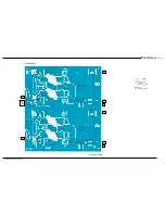
Page 75: ...L 1000 Technical Supplement PA Unit Component Side Parts Layout SRFJ150MP Q5001 5002 5003 5004 PAALM BIAS GND J5005 IN1 J5003 IN2 J5008 OUT1 J5004 OUT2 J5009 48V 1 J5001 E 1 J5002 48V 2 J5007 E 2 J500...

Page 76: ...VL 1000 Technical Supplement PA Unit Solder Side...

Page 77: ...VL 1000 Technical Supplement PA Unit Lot 5 Circuit Diagram...

Page 78: ...VL 1000 Technical Supplement PA Unit Lot 5 Notes...

Page 79: ...000 Technical Supplement PA Unit Lot 5 Component Side Parts Layout SRFJ150MP Q5001 5002 5003 5004 PAALM BIAS GND J5005 IN1 J5003 IN2 J5008 OUT1 J5004 OUT2 J5009 48V 1 J5001 E 1 J5002 48V 2 J5007 E 2 J...

Page 80: ...VL 1000 Technical Supplement PA Unit Lot 5 Solder Side...

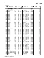
Page 81: ...M43 2X7R104K200PT K22237801 1 C 5027 CHIP CAP 0 1uF 200V X7R GRM43 2X7R104K200PT K22237801 1 C 5028 CHIP CAP 0 01uF 200V X7R GRM42 6X7R103K200PT K22231802 1 C 5029 CHIP CAP 0 1uF 200V X7R GRM43 2X7R10...

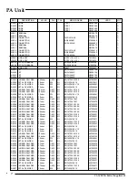
Page 82: ...70 2 R 5008 CARBON FILM RES 3 3kohm 1 6W 5 RD16TPJ332 3 3K J07225332 1 R 5008 CARBON FILM RES 2 2kohm 1 6W 5 RD16TPJ222 2 2K J07225222 2 R 5009 CARBON FILM RES 3 3kohm 1 6W 5 RD16TPJ332 3 3K J07225332...

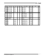
Page 83: ...R WIDE D12A RIB10X20X15 L0022411A 1 T 5003 COIL PWR WIDE D12A RIB21X42X40 L0022413A 1 T 5004 COIL PWR WIDE D12A TR20X10X10 L0022472 1 T 5005 COIL PWR WIDE D12A RIB10X20X15 L0022411A 1 T 5006 COIL PWR...

Page 84: ...VL 1000 Technical Supplement PA Unit Notes...

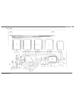
Page 85: ...VL 1000 Technical Supplement Display Unit Circuit Diagram...

Page 86: ...VL 1000 Technical Supplement Display Unit Notes...

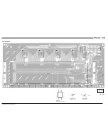
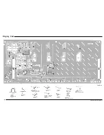
Page 87: ...VL 1000 Technical Supplement Display Unit Parts Layout PW SW 12V S2 S1 GND J6001 LCD Side HM62832HP 25 Q6010 6027 LC79400D Q6002 6003 6004 6005 TC74HC245AF Q6030 6031...

Page 88: ...S BK Q6008 TC74HC245AF Q6028 6029 6032 6033 6034 6035 6036 6037 TC74HC138F Q6026 TC74HC00AF Q6011 LA5310M Q6006 M51945BFP Q6015 NJU7662M Q6025 TC7W32F Q6009 L78M05T Q6014 2SA1213Y NY Q6022 6024 2SC404...

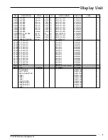
Page 89: ...GRM40B104M25PT K22140811 1 C 6024 CHIP CAP 0 1uF 25V B GRM40B104M25PT K22140811 1 C 6025 CHIP CAP 0 1uF 25V B GRM40B104M25PT K22140811 1 C 6026 CHIP CAP 0 1uF 25V B GRM40B104M25PT K22140811 1 C 6027 T...

Page 90: ...4HC245AF TP2 G1091274 1 Q 6031 IC TC74HC245AF TP2 G1091274 1 Q 6032 IC TC74HC245AF TP2 G1091274 1 Q 6033 IC TC74HC245AF TP2 G1091274 1 Q 6034 IC TC74HC245AF TP2 G1091274 1 Q 6035 IC TC74HC245AF TP2 G1...

Page 91: ...RES 82ohm 1 6W 5 RD16PJ820 82 J01225820 3 S 6001 TACT SWITCH SKHHAM N5090064 1 S 6002 TACT SWITCH SKHHAM N5090064 1 S 6003 TACT SWITCH SKHHAM N5090064 1 S 6004 TACT SWITCH SKHHAM N5090064 1 S 6005 TAC...

Page 92: ...VL 1000 Technical Supplement Display Unit Notes...

Page 93: ...VL 1000 Technical Supplement ANT SW Unit Circuit Diagram...

Page 94: ...VL 1000 Technical Supplement ANT SW Unit Notes...

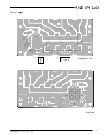
Page 95: ...VL 1000 Technical Supplement ANT SW Unit Parts Layout GND ANT0 ANT1 ANT2 ANT3 J7001 NO ANT GND J7006 Component Side Chip Side...

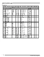
Page 96: ...VL 1000 Technical Supplement ANT SW Unit Parts List REF DESCRIPTION VALUE WV TOL LAY ADR YAESU P N MFGR S DESIG VERS LOT...

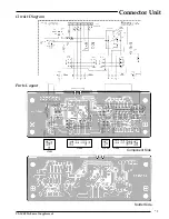
Page 97: ...00 Technical Supplement Connector Unit Solder Side A2 B2 C2 D2 INH2 TXD RXD GND FSET J7504 J7505 13 5V GND A1 B1 C1 D1 INH1 5V GND PSCNTL 12V J7503 GND PTT J7506 Component Side Circuit Diagram Parts L...

Page 98: ...VL 1000 Technical Supplement Connector Unit Parts List REF DESCRIPTION VALUE WV TOL LAY ADR YAESU P N MFGR S DESIG VERS LOT...

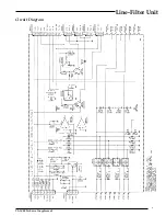
Page 99: ...VL 1000 Technical Supplement Line Filter Unit Circuit Diagram...

Page 100: ...VL 1000 Technical Supplement Line Filter Unit Notes...

Page 101: ...s Layout Solder Side GND FAN A J8004 FAN B GND J8005 FAN C GND J8006 GND PSCNTL 12V J8002 TX RL FAN SW VD M ID M PS ALM LOW GND 12V 12V J8003 12V 12V E LOW PS ALM REMOTE FQ J8001 Component Side M5218A...

Page 102: ...VL 1000 Technical Supplement Line Filter Unit Notes...

Page 103: ...5 1 D 8003 SURGE ABSORBER DSP201M S00B Q9000375 1 D 8004 SURGE ABSORBER DSP201M S00B Q9000375 1 D 8005 SURGE ABSORBER DSP201M S00B Q9000375 1 J 8001 CONNECTOR SC25 07WS P0090626 1 J 8002 CONNECTOR SC2...

Page 104: ...RES 220ohm 1 6W 5 RD16PJ221 220 J01225221 1 R 8007 CARBON FILM RES 10kohm 1 6W 5 RD16PJ103 10K J01225103 1 R 8008 CARBON FILM RES 1kohm 1 4W 5 RD14TJ102 1K J01245102 1 R 8009 CEMENT RES 0 01ohm 3W 10...

Page 105: ...VL 1000 Technical Supplement Sensor Unit Circuit Diagram Parts Layout SMB0 GND SMB1 SMB2 GND SMB3 J8503 GND SMB0 VCC GND SMA0 VCC J8501 SMA3 GND SMA2 SMA1 GND SMA0 J8502 Component Side Solder Side...

Page 106: ...ASSY A0897 T9206661 1 J 8502 WIRE ASSY A0897 T9206661A 5 J 8503 WIRE ASSY A0897 T9206662 1 J 8503 WIRE ASSY A0897 T9206662A 5 Q 8501 PHOTO INTERRUPTOR GP1A53HR G0090028 1 Q 8502 PHOTO INTERRUPTOR GP1A...

Page 107: ...VL 1000 Technical Supplement Jack Unit Solder Side Parts Layout GND PTT ALC J9005 GND PTT JP9001 Component Side Circuit Diagram...

Page 108: ...VL 1000 Technical Supplement Jack Unit Parts List REF DESCRIPTION VALUE WV TOL LAY ADR YAESU P N MFGR S DESIG VERS LOT...

Page 109: ...D Parts List RELAY UNIT PCB with Components CB0481001 Printed Circuit Board FR002220A 1 Printed Circuit Board FR002220B 7 C 9501 CERAMIC CAP 0 01uF 16V Y EP050Y103N A K28129001 1 J 9501 CONNECTOR SC25...

Page 110: ...VL 1000 Technical Supplement Relay Unit Notes...

Page 111: ...ment Filter Unit AC Power Supply VP 1000 Circuit Diagram Parts Layout Solder Side Component Side 12V 12V 12V COM 48V 33V ALARM REMOTE1 FG JP1003 12V 12V 12V COM 48V 33V ALARM REMOTE1 FG JP1001 VP 1000...

Page 112: ...VL 1000 Technical Supplement Filter Unit AC Power Supply VP 1000 Notes...

Page 113: ...VL 1000 Technical Supplement Filter Unit AC Power Supply VP 1000 Parts List REF DESCRIPTION VALUE WV TOL LAY ADR YAESU P N MFGR S DESIG VERS LOT...

Page 114: ...VL 1000 Technical Supplement Filter Unit AC Power Supply VP 1000 Notes...

Page 115: ......

Page 116: ......

Page 117: ......

Page 118: ......

Page 119: ......

Page 120: ......

Page 121: ......

Page 122: ......

Page 123: ......

Page 124: ......

Page 125: ......

Page 126: ......

Page 127: ......

Page 128: ......

Page 129: ......

Page 130: ......

Page 131: ......

Page 132: ...Printed in Japan Copyright 2004 VERTEX STANDARD CO LTD All rights reserved E08979100 No portion of this manual may be reproducedwithoutthepermission of VERTEX STANDARD CO LTD...

Reviews: