background image

MAIN Software Update 


・ 

MAIN CPU Software Version


*Don't forget to write down (or save to a CF Card) any personal menu settings you have changed from 
the default before you start. Please see the DMU-2000 Data Management Operation Manual for the 
procedure to save your settings to a CF card. 


1.


Turn the FT

DX

5000 OFF and disconnect the power cable (or turn OFF the MAIN power switch 

rear panel). 

2.


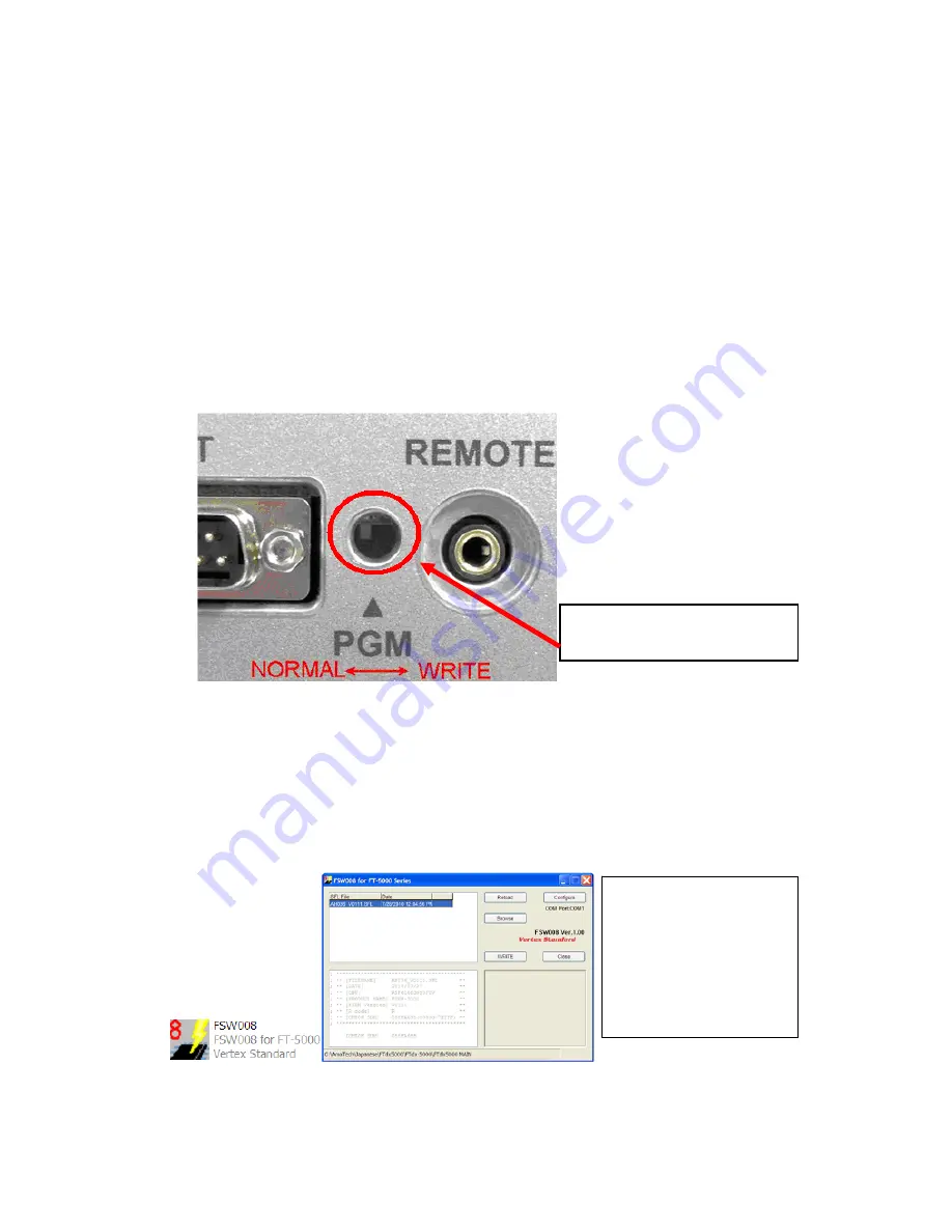
Locate the program switch thru the access hole on the back at the rear right corner of the radio. 
Carefully move the 

PGM-SW

 to the 

WRITE 

(program position). See Fig. 6.  

NOTE:

 always move the program switch before connecting the AC cable or turning the rear 

panel Power switch on, or the programming will not start.  


Fig. 6 

3.


Connect the serial straight through programming cable (DB9F to DB9F) to the serial port COM1 
in the back of your computer. Plug the DB9F connector to the CAT connector on the FT

DX

5000. 

If you use a USB to serial adapter, you might need to change the COM Port number. 

  
4.


Leave the FT

DX

5000 Front On/Off switch turned OFF and connect the power cable (or turn ON 

the rear panel MAIN power switch). 

5.


Now go to the desktop open FTdx5000 MAIN folder and find the 

FSW008

 icon as shown below. 

Double-click


the FSW008


icon, displayed on the Program Screen. 


NOTE:

 I

f you receive a 

“Communications Error !!!” 
message on your screen, click 
on the 

Configure

 box and 

choose a different COM port 
from the drop down menu. 
Then click the WRITE button 
again. Please refer to page 4 
for additional details.  

Carefully move the PGM-SW to 
the 

WRITE


(program position).


Summary of Contents for FTDX5000 - SOFTWARE UPDATE AND VERSION IDENTIFICATION

Page 1: ...17 10 OEL OLED Software Version 0110 3 23 10 SM 5000 Software Version 0107 3 23 10 DMU 2000 Software Version Option Please refer to the DMU 2000 update information on our website EDSP 5000 Programmin...

Page 2: ...lding the three buttons GEN 50 ENT turn the radio on The software version will be displayed See Fig 1 and 2 Fig 1 Fig 2 MAIN Software Version The version number will be shown on the VFD CLAR Clarifier...

Page 3: ...lay Left side See Fig 2 and 4 example OEL software version V0110 DMU 2000 Software Version The version number will be shown on the VFO A SELECT DIAL display Center See Fig 2 and 4 example DMU software...

Page 4: ...ication Error you may need to try another USB adapter cable or another computer 1 Turn the FTDX5000 rear panel Main Power switch OFF or disconnect the power cable 2 Make sure the USB to DB9 adapter ca...

Page 5: ...the programming will not start Fig 6 3 Connect the serial straight through programming cable DB9F to DB9F to the serial port COM1 in the back of your computer Plug the DB9F connector to the CAT connec...

Page 6: ...the NORMAL position See Fig 6 11 Reconnect the AC power cable or turn ON the rear MAIN power switch for FTDX5000 12 Press and hold in the FAST and LOCK keys while turning the radio back on This reset...

Page 7: ...9 pin CAT connector on the rear of the transceiver If you use a USB to serial adapter you might need to change the COM Port setting 3 Reconnect the AC power cable or turn ON the rear panel MAIN power...

Page 8: ...rear panel MAIN power switch 2 Connect a serial RS 232C DB9F to DB9F straight cable to the COM1 connector of your computer and the 9 pin CAT connector on the rear of the transceiver If you use a USB t...

Page 9: ...new software version will be displayed See Fig 2 SM 5000 Software Version 1 Turn the FTDX5000 OFF and disconnect the power cable or turn OFF the rear panel MAIN power switch 2 Locate the program swit...

Page 10: ...le Thru the access hole on the back of the SM 5000 move the PGM SW to the NORMAL position See Fig 10 12 Reconnect the AC power cable or turn ON the rear panel MAIN power switch for FTDX5000 13 Turn th...

Reviews: