17
•
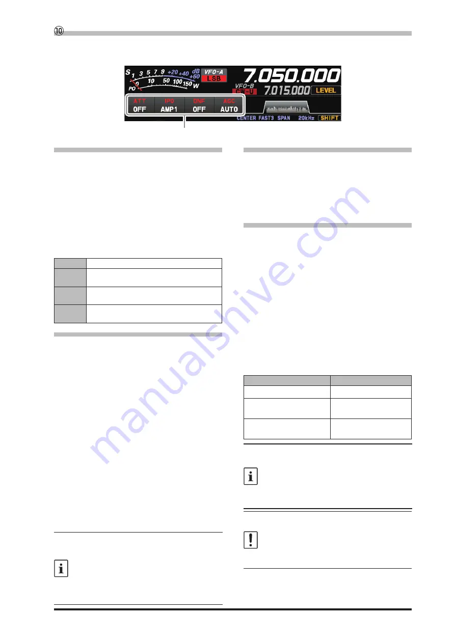
ATT (Attenuator)
Displays the current ATT (Amount of receive input
signal attenuation).
When the desired signal is extremely strong or
the noise level is high on a low frequency band,
activate the attenuator to reduce the incoming
signal or noise from the antenna.
After touching [ATT], touch the desired attenua-
tion amount.
The attenuator is set independently for each op-
eration band.
OFF
Attenuator is Off
6dB
The incoming signal power is reduced by 6dB
(Signal voltage reduced to 1/2)
12dB
The incoming signal power is reduced by 12dB
(Signal voltage reduced to 1/4)
18dB
The incoming signal power is reduced by 18dB
(Signal voltage reduced to 1/8)
•
IPO
The IPO (Intercept Point Optimization) function
can establish the gain of the RF amplifier section
to accommodate the connected antenna and the
received signal conditions. IPO can be selected
from three operating conditions.
AMP1:
One stage RF amplifier is connected.
This is a well-balanced operation of re-
ceiver sensitivity and characteristics (Ap-
proximately 10 dB gain).
AMP2:
Two RF amplifiers are connected in se-
ries to give top priority to sensitivity (Ap-
proximately 20 dB gain).
IPO:
The received signal is input to the IF mix-
er without passing through the RF ampli-
fier. This can greatly improve receiving,
especially in the harsh low band signal
environment.
After touching [IPO], touch the desired operating
condition.
•
IPO is set independently for each operation
band.
•
Normally, select “AMP1”.
•
The IPO can not only attenuate the input sig-
nal but also improve the intermodulation char-
acteristics. It is most effective to operate the
IPO first, and then use the ATT if the signal is
still too strong. The noise level can be attenu-
ated and S/N greatly improved.
•
DNF (Digital NOTCH Filter)
The Digital NOTCH Filter (DNF) is an effective
beat-canceling filter that can null out a number
of interfering beat notes inside the receiver pass-
band.
Because this is an Auto-Notch feature, there is no
djustment knob associated with this filter.
•
AGC (Automatic Gain Control)
Displays the currently selected AGC setting.
The AGC system is designed to help compen-
sate for fading and other propagation effects. The
AGC characteristics can be individually set for
each operating mode. The basic objective of AGC
is to maintain a constant audio output level once
a certain minimum threshold of signal strength is
achieved.
After touching [AGC], touch the desired time con-
stant.
● AGC can be set for each operation band.
● The “AUTO” selection mode selects the opti
-
mum receiver-recovery time for the reception
mode.
Operating Mode
AUTO AGC Selection
LSB / USB / AM / AM-N
SLOW
CW-L / CW-U / FM / FM-N
DATA-FM / D-FM-N
FAST
RTTY-L / RTTY-U
DATA-L / DATA-U / PSK
MID
Normally, AGC is set to “AUTO”, which auto-
matically selects the time constant according to
the received signal type, but when receiving a
weak signal or when there is noise and fading,
the AGC action may be changed according to
the reception condition at that time. Change the
time constant to make received signals most
audible
Several aspects of AGC performance may be
configured via the Menu. However, because
AGC can have such a profound impact on over-
all receiver performance, we generally do not
recommend any changes to the AGC Menu se-
lections until you are thoroughly familiar with the
performance of the FT-710.
Important Receiver Settings
The status of various operations that are important during receive, are shown at the bottom of the display.
To change a setting, touch the appropriate location on the display.
Important setting items when receiving
Summary of Contents for FT-710
Page 1: ...Operation Manual FT 710...
Page 2: ......


