PLL & Transmitter
Set up the test equipment as shown below for trans
mitter alignment Adjust the supply voltage to 12.0V
for all steps except Transmitter Output Power.
PLL
VC V (Varactor Control Voltage)
( 1 ) Connect the DC voltmeter between C4 1 7 on the
PLL Unit and chassis ground.
(2) Set the transceiver to 1 44.00 MHz. Key the trans
mitter and adjust transformer T50 1 on the VCO
Buffer Unit for 1 1 .5 ± 0.05 V DC on the voltmeter.
(3) While receiving on 144.00 MHz, adjust trimmer
TC50 1 on the VCO Unit for 0.8 ± 0.05 V DC.
(4) Tune the transceiver to the high band edge and
confirm the correct high-end VCV for the trans
ceiver version being aligned, in both transmit and
receive, as follows:
Version High Band Edge Tx VCV
Rx VCV
A, C & E
148.000 MHz
< 1 .6 v
< 1 .3 v
B & D
146.000 MHz
<1 .5 v
< 1 .2 v
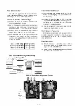
PLL & Transmitter Alignment Setup
50 - ohm
Dummy Load
Freq. Counter
S pectrum
Ara l izer.
Osc i l loscope
ANf
In l ine
Wattmeter
Dev iat i on
Meter
AF
M i l l ivo l tmeter
n
n ri MIC
=
=
=
AF Generator
AF
M i l l ivol tmeter
Regulated
1 2 V P S U
Transmitter Output Power
( 1 ) Tune the transceiver to band center ( 145 or 146
MHz), and select high power output (LOW switch
not depressed).
(2) Increase the supply voltage to 1 2.5 V, and then
adjust VR2005 on the Mother B oard for peak out
put power on the wattmeter (at least 5 watts with
less than 1 . 5 A supply current).
(3) Now press the LOW button, and adjust VR2005
(again), this time for 0.5 ± 0. 1 watt.
PLL Reference Frequency
With the transceiver tuned to band center ( 145 or
146 MHz), adjust TC40 1 on the PLL Unit, if necessary,
so the display frequency matches the frequency counter
when transmitting.
Modulation Level
( 1 ) With the transceiver tuned to band center ( 145 or
1 46 MHz), adjust the AF generator for 25-mV
output at 1 kHz to the MIC jack.
(2) Adjust VR2004 on the Mother B oard for ± 4.8-kHz
deviation on the deviation meter.
PLL & Transmitter Alignment Points
T s o 1
TC s o 1
V R 2 o o s
V R 2 0 0 4
TC 4 0 1
Summary of Contents for FT-23R MKII
Page 4: ......
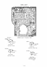
Page 13: ...CNTL UNIT obverse view of display side reverse view of microprocessor side 1 9 ...
Page 26: ......


