


9
4.
Apply solder to the joint, not the tip when soldering. The flux is naturally caustic
and thus will eat away the tip.
5.
Never clean the tip with a file or abrasive materials.
6.
Do not use fluxes which contain chloride or acid. Use only rosin or resin activated
fluxes.
7.
If an oxide film forms on the tip, it can be removed by careful buffing with a
600-800 grit emery cloth, isopropyl alcohol or equivalent and then wrapping rosin
core solder around the newly exposed surfaces. Coat the tinned areas with rosin-core
solder after the resin-core has melted.
NEW TIPS
Applying the following steps will lead to optimum life.
1.
Set temperature to min. then turn the main power switch to the “ON” position.
2.
Coat the tinned surfaces with rosin-core solder after reaching 25
0℃
.
3.
Set to desired temperature after allowing the unit to idle at 25
0℃
for 3 minutes.
4.
The iron will be ready for use once it reaches the preset temperature.
IMPORTANT
: Remove and clean the tip daily. If a new tip is installed, remove any
loose build up in the barrel assembly, otherwise the tip may fuse to the heating element
or retaining barrel.
MAINTENANCE
TIP MAINTENANCE AND DRESSING
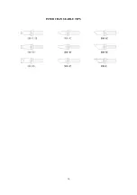
Tips can be changed or replaced simply by unscrewing the knurled nut barrel assembly.
The station must be switched off and allowed to cool before this operation as damage
may result if the system is left on without the tip in place!
After removing the tip, blow out any oxide dust that may have formed in the tip
retaining area of the barrel. Be careful to avoid getting this dust in your eyes. Replace
the tip and screw back the knurled nut barrel assembly using only firm hand pressure to
tighten. Pliers should only be used to tighten the nut to avoid burning your fingers, but
care should be taken not to over-tighten as this could damage the element.
GENERAL CLEANING
The outer cover of the iron and station may be cleaned with a damp cloth using small
amounts of liquid detergent. Never submerse the unit in liquid or allow any liquid to
enter the case of the station. Never use any solvent to clean the case.
SERVICE
If the iron or station should become faulty or, for some reason not operate normally, the
system should be returned to the service department of your authorized dealer or service
agent. Or a similarly qualified person in order to avoid a hazard.


