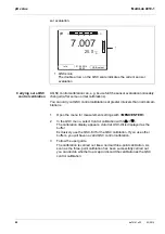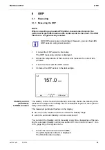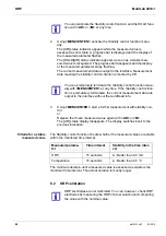
background image

MultiLab 4010-1

pH value

ba76141e03

03/2014

29

Criteria for a stable

measured value

The 

Stability control

 function checks whether the measured values are stable 

within the monitored time interval. 

The minimum duration until a measured value is assessed as stable is the 
monitored time interval. The actual duration is mostly longer.

5.1.2 Measuring the temperature

For reproducible pH measurements, it is essential to measure the temperature 
of the test sample. 

IDS sensors measure the temperature with a temperature sensor integrated in 
the IDS sensor.

You can terminate the 

Stability control

 function and the HOLD func-

tion with 

<AR>

 or 

<M>

 at any time. 

2.

Using 

<MENU/ENTER>

, activate the 

Stability control

 function manu-

ally.
The [AR] status indicator appears while the measured value is 
assessed as not stable. A progress bar is displayed and the display of 
the measured parameter flashes.
The [HOLD][AR] status indicator appears as soon as a stable mea-
sured value is recognized. The progress bar disappears and the display 
of the measured parameter stops flashing. 
The current measurement data is output to the interface. Measurement 
data meeting the stability control criterion is marked by AR.

You can prematurely terminate the 

Stability control

 function manu-

ally with 

<MENU/ENTER>

 at any time. If the 

Stability control

 func-

tion is prematurely terminated, the current measurement data are 
output to the interface without the AutoRead info.

3.

Using 

<MENU/ENTER>

, start a further measurement with stability con-

trol.
or
Release the frozen measured value again with 

<AR>

 or 

<M>

.

The [AR] status display disappears. The display switches back to the 
previous indication. 

Measured 
parameter

Time interval

Stability in the time inter-
val

pH value

15 seconds

 : Better than 0.01 pH

Temperature

15 seconds

 : Better than 0.5 °C

Summary of Contents for YSI MultiLab 4010P-1

Page 1: ...OPERATIONS MANUAL ba76141e03 03 2014 MultiLab 4010 P 1 DIGITAL METER FOR IDS SENSORS PH ORP D O COND 4010P 1 4010 1 4010 1 Printermodul 4010P 1...

Page 2: ...1 For the most recent version of the manual please visit www ysi com Contact YSI 1725 Brannum Lane Yellow Springs OH 45387 USA Tel 1 937 767 7241 800 765 4974 Email environmental ysi com Internet www...

Page 3: ...Requirements for safe operation 12 2 2 3 Unauthorized use 12 3 Commissioning 13 3 1 Scope of delivery 13 3 2 Power supply 13 3 3 Initial commissioning 13 3 3 1 Inserting the batteries 14 3 3 2 Connec...

Page 4: ...6 2 ORP calibration 44 7 Dissolved oxygen 45 7 1 Measuring 45 7 1 1 Measuring D O 45 7 1 2 Measuring the temperature 47 7 2 Calibration 47 7 2 1 Why calibrate 47 7 2 2 When to calibrate 47 7 2 3 Cali...

Page 5: ...intervals 74 10 3 Measured value data storage 76 10 3 1 Editing the measured value data storage 76 10 3 2 Erasing the measurement data storage 77 10 3 3 Measurement dataset 77 10 3 4 Storage location...

Page 6: ...Measuring ranges resolution accuracy 92 15 2 General data 92 16 Firmware update 94 16 1 Firmware update for the meter MultiLab 4010 1 94 16 2 Firmware Update for IDS Sensors 95 17 Glossary 96 18 Inde...

Page 7: ...measurements quickly and reliably The MultiLab 4010 1 provides the maximum degree of operating comfort reli ability and measuring certainty for all applications The MultiLab 4010 1 supports you in yo...

Page 8: ...nsors 1 3 1 IDS sensors IDS sensors support the automatic sensor recognition show only the settings relevant to the specific sensor in the setting menu process signals in the sensor digitally so that...

Page 9: ...t datasets are always stored and output with the sensor name and sensor series number to assign calibration data to an IDS sensor Calibration data and calibration history are always stored and output...

Page 10: ...Overview MultiLab 4010 1 10 ba76141e03 03 2014...

Page 11: ...ds might be damaged if the actions mentioned are not taken 2 1 2 Safety signs on the meter Note all labels information signs and safety symbols on the meter and in the battery compartment A warning sy...

Page 12: ...ration Note the following points for safe operation The meter may only be operated according to the authorized use specified above The meter may only be supplied with power by the energy sources menti...

Page 13: ...ultiLab Importer 3 2 Power supply The MultiLab 4010 1 is supplied with power in the following ways Mains operation with the supplied power pack Battery operation 4 batteries 1 5 V Mignon type AA USB o...

Page 14: ...1 Open the battery compartment 1 on the underside of the meter 1 Battery compartment CAUTION Make sure that the poles of the batteries are positioned cor rectly The signs on the batteries must corres...

Page 15: ...ine voltage at the operating site must lie within the input voltage range of the original power pack see section 15 2 GENERAL DATA page 92 CAUTION Use original power packs only see section 15 2 GENERA...

Page 16: ...ensor On Off Switches the meter on or off M Selects the measured parameter Quits the settings CAL CAL__ Calls up the calibration procedure Displays the calibration data STO STO__ Saves a measured valu...

Page 17: ...CMC function 5 Sensor symbol calibration evaluation calibration interval 6 Measured temperature with unit 7 Status information meter 8 Softkeys and date time AR Stability control AutoRead is active H...

Page 18: ...sensors pH ORP conductivity D O 2 USB B device interface 3 Stirrer ProOBOD 4 Service interface 5 Power pack CAUTION Only connect sensors to the meter that cannot return any volt ages or currents that...

Page 19: ...f The meter performs a self test 2 Connect the sensor The meter is ready to measure 25 0 7 007 pH C 0 14 More 03 04 2013 08 00 4110 B09250001 pH resolution 0 001 mV resolution 0 1 Buffer YSI Calibrati...

Page 20: ...or not a password is required for the login to the meter If the Password menu item is grayed out no password is required for the login If the user administration function is activated the Login dialog...

Page 21: ...ighlighted position with Go to the next digit of the password with F2 When the password was completely entered confirm with MENU ENTER The login takes place If a sensor is connected the measured value...

Page 22: ...The selection is made with the keys The current selection is dis played with a frame Submenus The name of the submenu is displayed at the upper edge of the frame Sub menus are opened by confirming wit...

Page 23: ...nfirming with MENU ENTER Example Display the Cal ibration record function Messages Information is marked by the i symbol It cannot be selected Example General Interface Clock function Service informat...

Page 24: ...The instrument is in the setting mode 3 Select the System submenu with The current selection is displayed with a frame 4 Open the System submenu with MENU ENTER Calibration record Calibration data st...

Page 25: ...etting with MENU ENTER The meter switches to the measuring mode The selected language is active General Interface Clock function Service information Reset System 03 04 2013 08 00 Back Language English...

Page 26: ...nd date format The date format can be switched from the display of day month year dd mm yy to the display of month day year mm dd yy or mm dd yy After a fall of the supply voltage empty batteries the...

Page 27: ...nd MENU ENTER The time is set 7 If necessary set the Date and Date format The setting is made similarly to that of the time 8 To make further settings switch to the next higher menu level with F1 Back...

Page 28: ...the stability range when the automatic Stability control is switched off You can start the Stability control manually at any time irrespective of the set ting for automatic Stability control see secti...

Page 29: ...stable A progress bar is displayed and the display of the measured parameter flashes The HOLD AR status indicator appears as soon as a stable mea sured value is recognized The progress bar disappears...

Page 30: ...s correctly selected see section 9 1 1 SETTINGS FOR PH MEASUREMENTS page 59 Use one to five buffer solutions of the selected buffer set in any order Below calibration with YSI buffers YSI is described...

Page 31: ...ssary finish the calibration procedure as a single point calibra tion with M The calibration record is displayed For single point calibration the instrument uses the Nernst slope 59 2 mV pH at 25 C an...

Page 32: ...Thoroughly rinse the sensor with deionized water 16 Immerse the sensor in the next buffer solution 17 Start the measurement with MENU ENTER The measured value is checked for stability stability contro...

Page 33: ...ingle point calibration was set in the menu the calibration proce dure is automatically finished with the measurement of buffer solu tion 1 and the calibration record is displayed 1 Connect the pH sen...

Page 34: ...voltage display 10 If necessary finish the calibration procedure as a single point calibra tion with M The calibration record is displayed For single point calibration the instrument uses the Nernst...

Page 35: ...necessary finish the calibration procedure as a two point calibration with M The calibration record is displayed pH 4 035 24 8 C ConCal 2 01 07 2011 08 00 Buffer 18 Thoroughly rinse the sensor with de...

Page 36: ...to finish the calibration The calibration record is displayed or Continue calibrating using the next buffer with MENU ENTER After the fifth buffer has been measured the calibration is automat ically...

Page 37: ...y in the measured value display The calibration record is automatically transmitted to the interface after calibrating Menu item Setting func tion Description Calibration Calibration data stor age Dis...

Page 38: ...0 58 0 57 0 25 20 or 20 25 61 0 60 5 or 57 0 56 0 30 25 or 25 30 62 0 61 0 or 56 0 50 0 Clean the IDS sensor according to the sensor operating manual Error Error 30 or 30 62 0 or 50 0 Error eliminatio...

Page 39: ...lue needle 2 Marking lines for all nominal buffer values used with the last valid cali bration 3 Measuring range for which a valid calibration is available Measured values in this range are suitable f...

Page 40: ...ffer solutions It covers the measuring range of the sensor pH 2 to pH 11 The QSC initial calibration determines the actual condi tion of the sensor and stores it as a reference in the sensor To meet t...

Page 41: ...ensor evaluation with the sensor symbol for this sensor 1 Open the menu for measurement settings with MENU ENTER 2 In the QSC menu select First calibration with The calibration display appears AutoCal...

Page 42: ...7 pH C 0 14 01 02 2014 08 00 Info USB output 1 Open the menu for measurement settings with MENU ENTER 2 In the QSC menu select Control calibration with The calibration display appears AutoCal QSC Kit...

Page 43: ...e is outside the stability range when the automatic Stability control is switched off You can start the Stability control manually at any time irrespective of the set ting for automatic Stability cont...

Page 44: ...rogress bar disappears and the display of the measured parameter stops flashing The current measurement data is output to the interface Measurement data meeting the stability control criterion is mark...

Page 45: ...ultiLab 4010 1 measures the current air pressure During calibration the air pressure correction function is automatically activated For measurement the air pressure correction is applied if the parame...

Page 46: ...s indicator is displayed The HOLD function is active You can terminate the Stability control function and the HOLD func tion with AR or M at any time 2 Using MENU ENTER activate the Stability control...

Page 47: ...and stores the current values of the zero point and slope 7 2 2 When to calibrate When the calibration interval has expired When your accuracy requirements are especially high Routinely within the fra...

Page 48: ...IDS D O sensor into the calibration vessel with water vapor saturated air As the calibration vessel use a BOD bottle that contains a small amount of clean water approx 40 ml The sensor must not be imm...

Page 49: ...easured value display with MENU ENTER 1 Connect the IDS D O sensor to the meter 2 Check the selected calibration type and selected number of calibration points in the sensor setting menu and if necess...

Page 50: ...brating in water vapor saturated air Cal Put the IDS D O sensor into the calibration vessel with water vapor saturated air As the calibration vessel use a BOD bottle that contains a small amount of cl...

Page 51: ...alibration menu press the MENU ENTER key in the measured value display 9 Wait for the AutoRead measurement to be completed audio signal When calibrating in water vapor saturated air Cal The calibratio...

Page 52: ...cords with Output the displayed calibra tion record to the interface with F2 USB output Output all calibration records to the interface with F2__ USB output Quit the display with F1 Back or MENU ENTER...

Page 53: ...n the menu for the parameter TDS Stability control AutoRead HOLD function The stability control function AutoRead continually checks the stability of the measurement signal The stability has a conside...

Page 54: ...A progress bar is displayed and the display of the measured parameter flashes The HOLD AR status indicator appears as soon as a stable mea sured value is recognized The progress bar disappears and the...

Page 55: ...to EN 27 888 Linear temperature compensation Lin with adjustable coefficients of 0 000 3 000 K No temperature compensation off Application tips Select the following temperature compensations given in...

Page 56: ...cell constant calibration in control standard You can determine the actual cell constant of the IDS conductivity sensor by calibrating with the control standard in the following range 0 450 0 500 cm 1...

Page 57: ...measured value is checked for stability stability control The AR status indicator is displayed The measured parameter flashes 6 Wait for the end of the measurement with stability control HOLD AR statu...

Page 58: ...ecord USB output Calibration Calibration data storage Output to RS232 USB Outputs the calibration data storage to the interface Menu item Setting function Description Display Calibration record Cell c...

Page 59: ...s see section 9 1 2 BUFFER SETS FOR CALIBRATION page 60 and section 5 2 PH CALIBRATION page 30 Calibration Single point calibration yes no Quick calibration with 1 buffer Calibration Calibra tion inte...

Page 60: ...ion 0 1 1 Resolution of the mV display Reset Resets all sensor settings to the delivery condition see sec tion 9 6 1 RESETTING THE MEASUREMENT SETTINGS page 70 Menu item Possible setting Description N...

Page 61: ...995 4 005 7 002 9 208 25 C 13 Fisher 2 007 4 002 7 004 10 002 25 C 14 Fluka BS 4 006 6 984 8 957 25 C 15 Radiometer 1 678 4 005 7 000 9 180 25 C 16 Baker 4 006 6 991 10 008 25 C 17 Metrohm 3 996 7 003...

Page 62: ...ibration interval The calibration interval is set to 7 days in the factory You can change the interval 1 999 days 22 Reagecon 20 2 000 4 000 7 000 10 000 13 000 20 C 23 Reagecon 25 2 000 4 000 7 000 1...

Page 63: ...en the settings display the required measured parameter in the measured value display and press the MENU ENTER key After completing the settings switch to the measured value display with M Default set...

Page 64: ...ensor cap For details see section 9 3 2 ENTER SENSOR CAP COEFFICIENTS page 65 Salinity Sal cor rection on off Manual salt content correction for con centration measurements Salinity Salinity 0 0 70 0...

Page 65: ...ion local is ideal for EU compliance When DO Saturation local is enabled an L will appear next to D O on the display D O mg L readings are unaffected by the selection of DO Saturation local The values...

Page 66: ...e last calibration records max 10 Calibration Calibration data storage Output to RS232 USB Outputs the calibration data storage to the interface Calibration Cali bration interval 1 150 999 d Calibrati...

Page 67: ...ible setting Description Cell constant 0 090 0 100 0 110 cm 1 Display and setting options for the cell constant Temp comp TC Method nLF Lin off Procedure for temperature compen sation see section 8 2...

Page 68: ...emperature unit degrees Celsius or degrees Fahrenheit All temperature values are displayed with the selected unit System General Stability con trol on off Switches on or off the automatic stability co...

Page 69: ...off function The instrument has an automatic shutoff function in order to save the batteries see section 9 5 1 SYSTEM page 68 The automatic shutoff function switches off the meter if no key is pressed...

Page 70: ...nction The sensor settings are reset under the Reset menu item in the menu for cali bration and measurement settings To open the settings display the required measured parameter in the measured value...

Page 71: ...o open the settings display the required measured parameter in the measured value display and press the MENU ENTER key Conductivity The following settings for conductivity measurements are reset to th...

Page 72: ...R key 9 6 2 Resetting the system settings The following system settings can be reset to the default condition The system settings are reset in the menu Storage config System Reset To open the Storage...

Page 73: ...utput to the USB interface If the data storage is full When all data storage locations are occupied it is not possible to continue stor ing Then you can e g transmit the stored data to a PC see sectio...

Page 74: ...Graphical display of the data storage usage ID number 1 Interval 30 s Duration 180 min continue 0d03h00min 0 1d17h33min Automatic data storage 1 2 3 03 04 2013 08 00 Back Menu item Possible setting De...

Page 75: ...d as follows to switch off the automatic data storage function before the adjusted storage duration has expired 1 Remaining storage duration 2 Graphical display of the storage duration If the automati...

Page 76: ...rectly with the RCL or RCL__ key Settings The settings are explained here using the manual data storage as an example The same settings and functions are available for the automatic data storage Menu...

Page 77: ...rage see section 10 3 1 EDITING THE MEASURED VALUE DATA STORAGE page 76 10 3 3 Measurement dataset A complete dataset includes Date time Meter name series number Sensor name series number Manual data...

Page 78: ...hile storing stable measured value Otherwise the AR dis play is missing Calibration evaluation 4 levels or no evaluation or QSC percentage 10 3 4 Storage locations The MultiLab 4010 1 meter has two me...

Page 79: ...or installation of the USB driver PC with at least one free USB connection and CD ROM drive Windows 2000 Windows XP Windows Vista or Windows 7 1 Output the current measurement data to the USB B interf...

Page 80: ...ltaneously with every auto matic storage process see section 10 2 AUTOMATIC DATA STORAGE AT INTERVALS page 74 Stored mea sured values manual Displayed dataset with F2 USB output after calling up from...

Page 81: ...1e03 03 2014 81 11 6 BOD Analyst Pro With the aid of the BOD Analyst Pro software you can administrate BOD measurement on the PC and automatically calculate the measured values More detailed informati...

Page 82: ...Transmitting data USB interfaces MultiLab 4010 1 82 ba76141e03 03 2014...

Page 83: ...the keys ON FEED and OFF 3 Lever to open the paper compartment 4 Lid of the paper compartment 2 1 3 4 1 Connect the power pack to the MultiLab 4010P 1 The LED lights up green The printer is ready for...

Page 84: ...1 Changing the roll of paper thermal paper Menu item Possible set ting Description System Printer Font size 12x20 8x16 7x16 Select the font size for the printer A print sample character set of the pr...

Page 85: ...om the meter Function automatic storing at intervals with long intervals is switched on Switch off the function see section 10 2 AUTOMATIC DATA STORAGE AT INTERVALS page 74 No paper available Insert a...

Page 86: ...th normal batteries or with rechargeable batteries Ni MH In order to charge the batteries an external charging device is required 1 Open the battery compartment 1 on the underside of the meter 1 Batte...

Page 87: ...ter must be returned to the disposal or return system statutory in your country If you have any questions please contact your supplier Dispose of used batteries according to the local regulations of y...

Page 88: ...ion Remove air bubble Cable broken Exchange IDS pH sensor Gel electrolyte dried out Exchange IDS pH sensor Cause Remedy IDS pH sensor The values determined for zero point and slope of the pH sensor ar...

Page 89: ...sensor test sample Conductivity too low Use suitable IDS pH sensor Temperature too high Use suitable IDS pH sensor Organic liquids Use suitable IDS pH sensor Cause Remedy IDS pH sensor pH sensor unsu...

Page 90: ...ad of a temperature value Keep to the temperature range for the test sample Defective sensor Calibrate Change sensor cap Replace sensor More information and instructions on cleaning and exchange of se...

Page 91: ...1 MAINTENANCE page 86 Cause Remedy Operating condition undefined or EMC load unallowed Processor reset Press the ENTER and On Off key simultaneously Cause Remedy E g a question by the service departme...

Page 92: ...anical structure Type of protection IP 43 Electrical safety Protective class III Test certificates CE cETLus Ambient conditions Storage 25 C 65 C Operation 5 C 55 C With the power pack connected 5 C 4...

Page 93: ...comply with the limits for a Class A digital device pursuant to Part 15 of the FCC Rules These limits are designed to provide reasonable protection against harmful interference when the equipment is...

Page 94: ...VERSION IS IN THE METER OR IDS SENSOR PAGE 91 1 Install the downloaded firmware update on a PC An update folder is created in the Windows start menu If an update folder already exists for the meter o...

Page 95: ...R IDS SENSOR PAGE 91 1 Install the downloaded firmware update on a PC An update folder is created in the Windows start menu If an update folder already exists for the sensor or sensor type the new dat...

Page 96: ...activity divided by the unit of the molality The practical pH value is the value of a pH measurement Potentiometry Name of a measuring technique The signal depending on the mea sured parameter of the...

Page 97: ...TRef D O saturation Short name for the relative D O saturation Relation of the D O partial pressure in the test sample to the D O par tial pressure of air at the current air pressure Example 100 mean...

Page 98: ...of all settings of a measuring system Resolution Smallest difference between two measured values that can be dis played by a meter Stability control AutoRead Function to control the measured value sta...

Page 99: ...asured parameter 70 System settings 72 Display 17 F Firmware update 94 I Initial commissioning 13 Initialize 70 Interval for calibration 62 K Keys 16 M Measured value display 22 Measurement accuracy 6...

Page 100: ...03 03 2014 Temperature measurement Conductivity 55 O2 47 pH 29 Three point calibration pH 32 35 Transmitting data 79 automatic 80 manual 80 Transmitting measured values 79 Two point calibration pH 31...

Page 101: ...MultiLab 4010 1 Index ba76141e03 03 2014 101...

Page 102: ...9 10 531 9 930 9 362 8 826 9 0 11 559 10 907 10 290 9 707 9 156 8 636 10 0 11 288 10 656 10 058 9 493 8 959 8 454 11 0 10 027 10 415 9 835 9 287 8 769 8 279 12 0 10 777 10 183 9 621 9 089 8 586 8 111...

Page 103: ...5 842 5 576 5 321 5 078 41 0 6 312 6 026 5 753 5 493 5 243 5 005 42 0 6 213 5 934 5 667 5 411 5 167 4 993 43 0 6 116 5 843 5 581 5 331 5 091 4 861 44 0 6 021 5 753 5 497 5 252 5 017 4 793 45 0 5 927 5...

Page 104: ...3 668 8 89 2 892 3496 1066 88 26 03 661 2 88 1 881 3804 1106 87 25 73 653 6 87 2 871 4115 1254 86 25 43 646 86 1 861 4430 1350 85 25 13 638 4 85 1 851 4747 1447 84 24 84 630 8 84 1 841 5067 1544 83 24...

Page 105: ...ning a product for service include the Product Return form with cleaning certification The form must be completely filled out for an YSI Service Center to accept the instrument for service The Product...

Page 106: ...Contact Information MultiLab 4010 1 106 ba76141e03 03 2014...

Page 107: ......

Page 108: ...and return water to the environment and we help people use water efficiently in their homes buildings factories and farms In more than 150 countries we have strong long standing relationships with cus...

Reviews: