Xylem G&L A-C 8300 Series Instruction Manual Download Page 16

Diagram

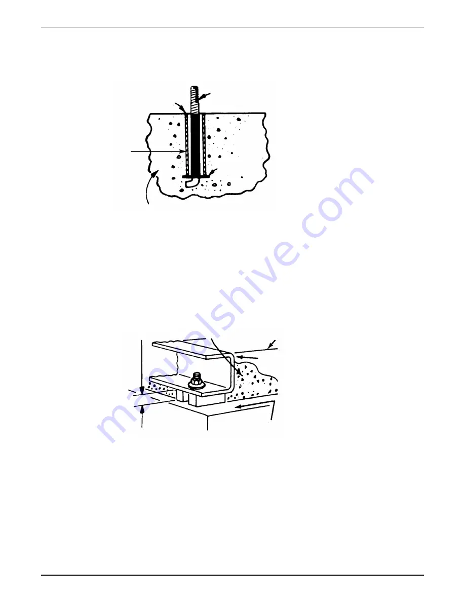
• An optional 4–inch long tube around the bolts at the top of the concrete allows some

flexibility in bolt alignment to match the holes in the baseplate.

• Allow enough bolt length for grout, shims, lower baseplate flange, nuts, and washers.

2

4

1

3

5

1. Foundation bolt

2. Pipe sleeve

3. Washer

4. Built-up concrete foundation

5. Optional 4–inch tube around the bolts

4.1.4  Level the base on a concrete foundation

1. Place the pump on its concrete foundation.
2. Place 1.00 in./(25.40 mm) thick steel shims or wedges on both sides of each anchor

bolt in order to support the pump .
This also provides a means of leveling the base.
Add and remove shims under the base to level and plumb the pump shaft and flanges.
The baseplate does not have to be level.

4

1

5

2

3

6

7

1. Locate the shims to allow removal after grouting.

2. Grout only to top of base rail

3. Pump base rail

4. Grout

5. Concrete foundation

6. 1” (25.40 mm) Gap

7. Allow 1” for shims. Place on both sides of anchor bolts.

3. Draw anchor bolts tight against the base and observe pump and motor shafts or

coupling hubs for alignment.
Temporarily remove the coupling guard for checking alignment.

4. If the alignment needs improvement, add shims or wedges at appropriate positions

under the base so that retightening of anchor nuts shifts shafts into closer alignment.
Repeat this procedure until a reasonable alignment is reached.
A reasonable alignment is that which is agreed upon by the pump contractor and the
accepting facility. Final alignment procedures are covered in “Alignment procedures.”

4  Installation

14

G&L Pumps Series A-C 8300 Base Mounted Centrifugal Pump INSTRUCTION MANUAL

Summary of Contents for G&L A-C 8300 Series

Page 1: ...INSTRUCTION MANUAL AC5658D G L Pumps Series A C 8300 Base Mounted Centrifugal Pump...

Page 2: ......

Page 3: ...undation requirements 13 4 1 4 Level the base on a concrete foundation 14 4 1 5 Grout the baseplate 15 4 2 Coupling alignment 15 4 2 1 Prepare for alignment 15 4 2 2 Align the pump using a straight ed...

Page 4: ...he mechanical seals and bearings without removing the upper half of the casing 31 6 7 Pre assembly inspections 33 6 7 1 Replacement guidelines 33 6 7 2 Shaft inspection 33 6 8 Dimensions 34 6 9 Reasse...

Page 5: ...of parts not provided by Xylem If there is a question regarding the intended use of the equipment please contact a Xylem representative before proceeding Do not change the service application without...

Page 6: ...als WARNING Do NOT exceed the maximum working pressure of the pump This information is listed on the nameplate of the pump Alert symbol This safety alert symbol is used in manuals and on the safety in...

Page 7: ...hin the work area Hard hat Safety goggles preferably with side shields Protective shoes Protective gloves Gas mask Hearing protection First aid kit Safety devices NOTICE Never operate a unit unless sa...

Page 8: ...with your fingers 2 Rinse the eyes with eyewash or running water for at least 15 minutes 3 Seek medical attention Chemicals or hazardous fluids on skin 1 Remove contaminated clothing 2 Wash the skin...

Page 9: ...ey will be packaged in a separate container and shipped with the pump or attached to the base plate Shaft alignment Shafts are in alignment when the unit is shipped however misalignment can occur due...

Page 10: ...ution to ensure the weight is balanced equally distributed across both forks When the baseplate of the assembly is structural channel construction the pump and base plate should be set in place first...

Page 11: ...ed shutdown after the unit is in operation the following requirements for short term storage apply Store in a covered and dry location Store the unit free from excessive cold or heat below 32 F and ab...

Page 12: ...s normally utilize the pumped liquid to lubricate the seal faces This method is preferred when the pumped liquid is neither abrasive nor corrosive Intended applications WARNING This product can expose...

Page 13: ...eplate information The pump nameplate gives identification and rating information about the pump Permanent records for this pump are kept by the serial number and it must be used will all corresponden...

Page 14: ...ed lifting points Lifting devices such as eyebolts slings and spreaders must be rated selected and used for the entire load being lifted Guideline Explanation comment Keep the pump as close to the liq...

Page 15: ...upply 9 Reducing valve 4 1 3 Foundation requirements Requirements A substantial foundation and footing should be built to suit local conditions and form a rigid support to maintain alignment The found...

Page 16: ...late does not have to be level 4 1 5 2 3 6 7 1 Locate the shims to allow removal after grouting 2 Grout only to top of base rail 3 Pump base rail 4 Grout 5 Concrete foundation 6 1 25 40 mm Gap 7 Allow...

Page 17: ...ollow these guidelines when you align the coupling Only perform alignment by moving or shimming the motor Make allowances for thermal expansion during cold alignment so that the coupling is aligned at...

Page 18: ...adius is permissible Feeler gauges 1 Insert feeler gauges between the coupling faces at various points around the circumference Do not rotate the shafts 2 Reposition the equipment until the difference...

Page 19: ...ipped However this dimension should be checked Refer to the coupling manufacturer s specifications supplied with the unit 1 Check the angular misalignment a Mount the dial indicator base to one coupli...

Page 20: ...erature then secure the pump and re check the alignment Make sure that you compensate for temperature accordingly NOTICE Elastomeric couplings are specifically designed to accommodate angular shaft mi...

Page 21: ...2 0 020 2 563 8 0 015 0 025 2 938 9 0 017 0 028 3 500 10 0 020 0 032 4 063 11 0 022 0 037 4 875 12 0 025 0 042 5 688 13 0 030 0 050 6 625 14 0 035 0 060 7 750 4 3 Piping checklists 4 3 1 Piping checkl...

Page 22: ...selected and installed so that pressure losses are minimized and sufficient liquid flows into the pump when it is started and operated Many NPSH problems can be directly attributed to improper suctio...

Page 23: ...ows the unbalanced loading of a double suction impeller due to the uneven flow around an elbow that is adjacent to the pump 1 2 3 4 5 1 Pump casing 2 Impeller 3 Pump suction flange 4 Suction elbow 5 W...

Page 24: ...2 1 1 No air pockets 2 Eccentric reducer 3 Gradual rise Figure 13 Gradual rise to the pump correct 1 1 Distance plus eccentric reducer straightens the flow Figure 14 Suction pipe above the pump correc...

Page 25: ...e pipe system in order to prevent premature failure at initial startup If temperatures of the pumped fluid will exceed 200 F 93 C then warm up the pump prior to operation Circulate a small amount of f...

Page 26: ...ing to assure that there are no leaks 2 Check and record pressure gauge readings for future reference 3 Check and record voltage amperage per phase and kw if an indicating wattmeter is available 4 Che...

Page 27: ...r can only come off from the outboard end 2 With the rotating element out of the casing remove the casing from the bedplate and turn 180 3 Set the rotating element back in the casing and reassemble th...

Page 28: ...Figure 17 Main joint bolts 5 Commissioning Startup Operation and Shutdown 26 G L Pumps Series A C 8300 Base Mounted Centrifugal Pump INSTRUCTION MANUAL...

Page 29: ...pe as recommended Six month inspections Perform these tasks every six months Take vibration readings on the bearing housings Compare the readings with the last set of readings to check for possible pu...

Page 30: ...on schedule Type of bearing First lubrication assembled pumps and replacement bearing frames First lubrication replacement bearings Lubrication interval pump polyurea based grease operating hours Grea...

Page 31: ...exTM N2 6 4 Shaft seal maintenance 6 4 1 Mechanical seal maintenance Keep in mind the following general rules regarding mechanical seal maintenance Refer to the instructions provided by the seal manuf...

Page 32: ...sides of the pump You must drain the system if no valves are installed 2 Open the drain valve Do not proceed until liquid stops coming out of the drain valve If liquid continues to flow from the drain...

Page 33: ...efore proceeding Open drain valve do not proceed until liquid stops coming out of the drain valve If liquid does not stop flowing from drain valve isolation valves are not sealing and should be repair...

Page 34: ...ling 5 Remove the socket head capscrews holding the gland plates to the stuffing boxes 6 Insert threaded rods into the tapped holes in the gland plate and install a fixture on the threaded rods to use...

Page 35: ...rotect machined surfaces while you clean the parts Failure to do so may result in equipment damage 6 7 1 Replacement guidelines Impeller replacement This table shows the criteria for replacing the imp...

Page 36: ...O rings and lip seals should be replaced with new parts during assembly All reusable parts should be cleaned of foreign matter before reassembly NOTE Reassemble the pump by starting on the outboard en...

Page 37: ...Use a flashlight and make sure the mechanical seal spring is searing properly into the spring holder and around the bellows of the mechanical seal before continuing 5 Slide the gland plate over the sh...

Page 38: ...knut and lockwasher are not installed on the inboard end of the pump shaft 13 Reinstall the coupler and check for alignment following the instructions found in the Coupling Alignment section of this m...

Page 39: ...s step is not followed properly 5 Assemble the impeller key in the shaft key slot Note For impeller with replaceable rings heat each new ring approximately 300 F 400 F for bronze and slide onto the im...

Page 40: ...et head capscrews to start the gland plate into the stuffing box To prevent the mechanical seal spring from pushing the gland plate back out of the stuffing box remove one long socket head capscrews a...

Page 41: ...the ball bearings using dry heat to 10 15 soluble oil and water or an induction heater CAUTION Do not exceed a temperature of 275 F 19 Using gloves slide the heating bearing onto the shaft against th...

Page 42: ...the coupler on the end of the shaft 25 Set the rotating element in the pump casing assuring correct rotation Locate both stuffing box tongues in their respective casing grooves Locate the pins in the...

Page 43: ...ing Alignment section of this manual Replace the coupler guard 6 9 3 Install the hex coupling guard 1 Check coupler alignment before proceeding Correct if necessary 2 Slide the inner guard into the ou...

Page 44: ...ings 1 set of gaskets O rings and grease seals 2 mechanical seals complete 1 set of shaft sleeves Parts should be ordered as far in advance of their use as possible since circumstances beyond the cont...

Page 45: ...entative and be prepared to provide this information 1 Complete nameplate data of pump and motor 2 Suction and discharge pipe pressure gauge readings 3 Ampere draw of the motor 4 A sketch of the pump...

Page 46: ...tatic lift may be too great Measure with mercury column or vacuum gauge while pump operates If static lift is too high liquid to be pumped must be raised or pump lowered Discharge head too high Check...

Page 47: ...d clean impeller Cavitation insufficient NPSH depending on installation 1 Increase positive suction head on pump by lowering pump 2 Sub cool suction piping at inlet to lower entering liquid temperatur...

Page 48: ...nlet check for pipe friction losses Static lift may be too great Measure with mercury column or vacuum gauge while pump operates If static lift is too high liquid to be pumped must be raised or pump l...

Page 49: ...lection of rotor by turning on bearing journals Total indicator run out should not exceed 0 002 on shaft and 0 004 on impeller wearing surface Mechanical failure of critical pump parts Check bearings...

Page 50: ...arranted only for the balance of the warranty period on the parts that were repaired or replaced Seller shall have no warranty obligations to Buyer with respect to any product or parts of a product th...

Page 51: ...repaired by third parties other than Seller or without Seller s written approval b subject to misuse misapplication neglect alteration accident or physical damage c used in a manner contrary to Selle...

Page 52: ...he dealer from whom you purchased the product or visit www xyleminc com for the name and location of the nearest dealer providing warranty service 8 Product warranty 50 G L Pumps Series A C 8300 Base...

Page 53: ......

Page 54: ......

Page 55: ......

Page 56: ...ork technologies and advanced analytics solutions for water electric and gas utilities In more than 150 countries we have strong long standing relationships with customers who know us for our powerful...

Reviews: