• EMC cable connectors: Generally available cable connectors can be used to ensure an
optimum EMC connection.
• EMC cable clamp: Clamps allowing for easy connection are supplied with the
adjustable frequency drive.
5.9 Motor connection
WARNING:
INDUCED VOLTAGE. Run output motor cables from multiple frequency converters
separately. Induced voltage from output motor cables run together can charge
equipment capacitors even with the equipment turned off and locked out. Failure to run
output motor cables separately could result in death or serious injury.
Be sure the following are adhered to:
Power-dependent specifications
.
• Comply with local and national electrical codes
• Connector plates are provided at the base of
IP21/54
and higher (NEMA 1/12) units
• Do not install power factor correction capacitors between the frequency converter and
the motor
• Do not wire a starting or pole-changing device between the frequency converter and
the motor
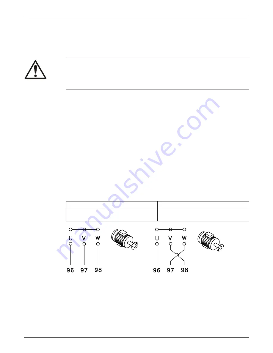
• Connect the 3–phase motor wiring to terminals 96 (U), 97 (V), and 98 (W)
• Ground the cable in accordance with grounding instructions provided
• Torque terminals in accordance with the information provided in
• Follow motor manufacturer wiring requirements
The motor must be connected to terminals U/T1/96, V/T2/97, W/T3/98. Ground to
terminal 99. All types of three-phase asynchronous standard motors can be used with an
adjustable frequency drive unit. The factory setting is for clockwise rotation with the
adjustable frequency drive output connected as follows:
Terminal number
Function
96, 97, 98, 99
Line power U/T1, V/T2, W/T3
Ground
Figure 62: Motor connections
• Terminal U/T1/96 connected to U-phase
• Terminal V/T2/97 connected to V-phase
• Terminal W/T3/98 connected to W-phase
The direction of rotation can be changed by switching two phases in the motor cable or
by changing the setting of [4–10] Motor Speed Direction. Motor Rotation Check can be
performed by using [1–28] Motor Rotation Check and following the steps that are shown
in the display.
5 Electrical Installation
52
Aquavar
®
Intelligent Pump Controller - 150 HP to 600 HP INSTRUCTION MANUAL
Summary of Contents for Aquavar
Page 1: ...INSTRUCTION MANUAL IM273 Rev C Aquavar Intelligent Pump Controller 150 HP to 600 HP...
Page 2: ......
Page 171: ......


