background image

9460/9460KP/9462/9462KP System Manual

5-2

Route Maintenance

This section describes the maintenance you can perform on the 9460/9462.

Fuse Replacement

The 9460/9462 has no accessible fuse. Return the unit to Xycom for fuse replacement.

Fan Filter Replacement

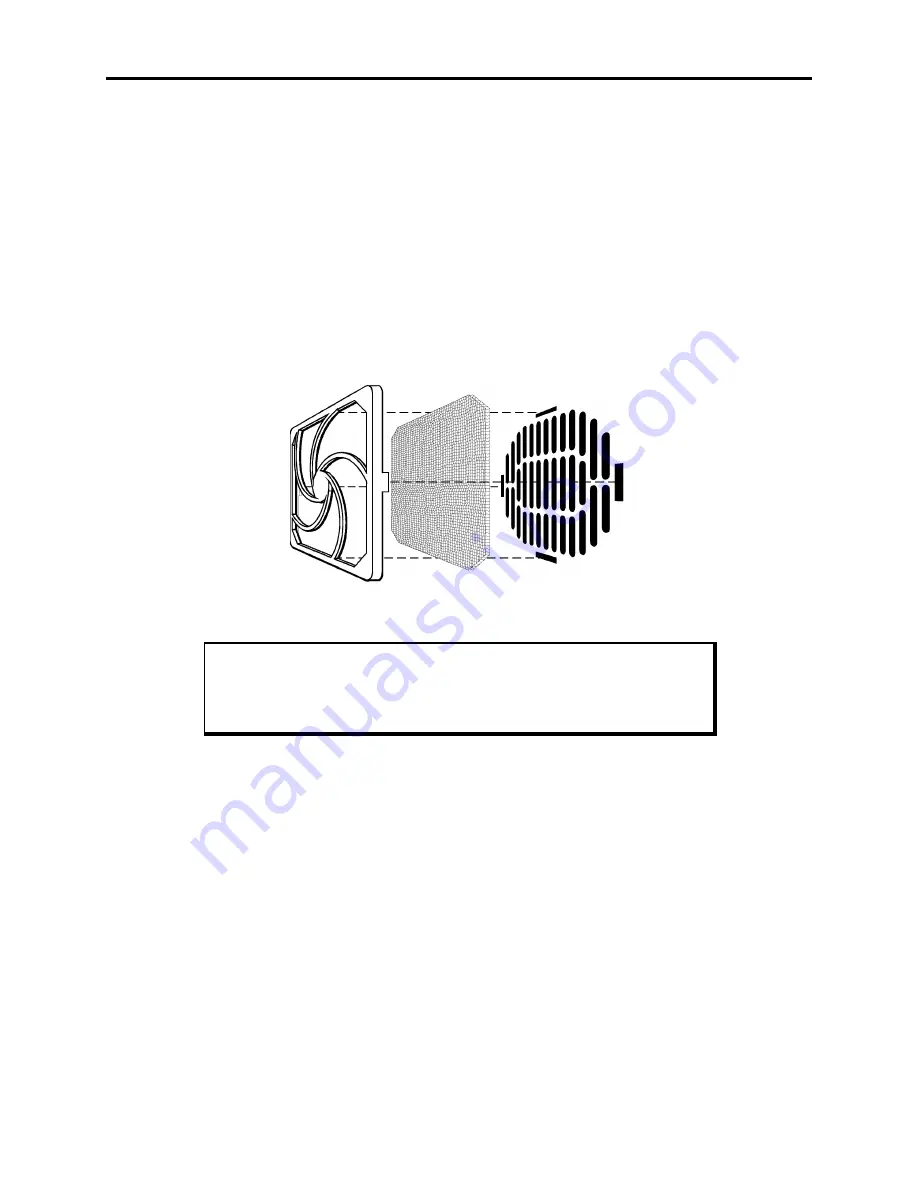
To change the fan filter, remove the grill and filter as illustrated in Figure Chapter 5 -1.
Clean or replace the filter and snap the assembly back into position.

Figure Chapter 5 -1. Fan Assembly

Caution

Do not operate the 9460/9462 without a fan filter. Dust build-up could
cause the unit to malfunction.

Summary of Contents for 9462

Page 1: ...9460 9460KP 9462 9462KP Flat Panel Industrial PCs P N 129398 001B 1998 XYCOM INC Printed in the United States of America...

Page 2: ...d States and other countries Copyright Information This document is copyrighted by Xycom Incorporated Xycom and shall not be reproduced or copied without expressed written authorization from Xycom The...

Page 3: ...stalling Internal Hardware Options 3 8 DRAM and Additional DRAM Single In line Memory Modules SIMMs 3 8 PC AT and PCI Boards 3 9 Installing External Hardware Options 3 9 External Floppy 3 9 Front Conn...

Page 4: ...llations 3 29 Definitions 3 31 Class I Locations 3 31 Class II Locations 3 31 Division 1 Locations 3 31 Division 2 Locations 3 32 Groups 3 32 Enclosures 3 33 Power Switch 3 33 Cable Connections 3 33 O...

Page 5: ...intenance 5 2 Fuse Replacement 5 2 Fan Filter Replacement 5 2 Chemical Compatibility 5 3 Compatible Lubricants 5 4 Compatible Cleaning Agents 5 5 Non compatible Cleaning Agents 5 5 Spare Parts List 5...

Page 6: ...Panel Display Bulbs D 1 9460 Units D 1 Kyocera STN Flat Panel Display model KCS6448HSTT X21 D 1 Sharp TFT Flat Panel Display model LQ10D421 D 3 9462 Units D 4 Mitsubishi TFT Flat Panel Display Model...

Page 7: ...y the following directions which relate to installation and configuration 1 All interface cables must include shielded cables Braid foil type shields are recommended Communication cable connectors mus...

Page 8: ...d combines all the functions of a complete IBM PC AT compatible computer on a single industrially hardened circuit board Refer to the Xycom CPU manual for more information on processor and hardware fe...

Page 9: ...ss I Division 2 hazardous locations Optional Features Following are optional features available for the units Touch screen resistive technology with less than 1 5 linearity error 9460 DRVNT Windows NT...

Page 10: ...strain relief of power cord 9460 9460KP 9462 9462KP manual CPU manual Utility disks Business reply card If you ordered the system with a touch screen installed you will also receive a touch screen dr...

Page 11: ...the contrast on the unit by using the contrast adjust keys on the front panel These keys are available on the STN passive color option only On the 9460KP and 9462KP hold the F A key and press the lef...

Page 12: ...setup menus are configured properly factory set configuration To enter the BIOS setup menus Press F2 after the POST RAM test has completed Make the necessary changes by following directions on the sc...

Page 13: ...female end of the AC power cable into the side of the unit and the male end into a properly grounded outlet 3 Connect the serial loopback connector s and the printer cable to the appropriate con nect...

Page 14: ...ocessor Test J Video Adjustments Test K Video Interface Test L Speaker Port Test M LPT1 Printer Port Test N LPT2 Printer Port Test O C Hard Drive Interface Test P D Hard Drive Interface Test Q A Flopp...

Page 15: ...internal and external components on the front and back panels of the unit to help you locate features relevant to installation Front Panel The 9460 9462 comes with a NEMA 4 4X 12 and IP65 sealed front...

Page 16: ...configuration against the configuration stored in the CMOS memory IR Infrared The IR port transceiver is located behind this window The 9460 9462 IR port is IrDA and ASKIR compliant You can connect t...

Page 17: ...The 9460KP 9462KP comes with a NEMA 4 4X 12 sealed front panel The panel pro tects the system s interior when the system is properly panel mounted Figure Chapter 3 2 illustrates the front panel with...

Page 18: ...ovide easy access to familiar routines F A keys can be used for alpha and symbol entry See the Customizing Keypad In serts section in this chapter for details on customizing your key pad inserts Numer...

Page 19: ...system only supports COM2 Therefore the touch screen will be on COM2 and COM2 will not be available for other use Keyboard Port The keyboard port is a PS 2 stacked mini din that allows you to attach...

Page 20: ...does not support simultaneous flat panel and CRT with an STN passive flat panel display Ethernet Port optional This port provides a 10BASE T 100BASE TX autosensing Ethernet connection Back Panel Figu...

Page 21: ...or and External Floppy Connector Feature Description Power Connector This is a three pin connector Refer to the special hazardous loca tion installation instructions later in this chapter External Flo...

Page 22: ...Hz outlet or a 24 VDC outlet whichever applies refer to the Hazardous Location Installations section later in this chapter 7 Turn on power to the system The system will boot up to the operating syste...

Page 23: ...the track 7 Replace the lid Installing External Hardware Options This section explains how to install the external hardware options available with the system Note When using the external floppy drive...

Page 24: ...ns using the 9000 RFC Rack Filler Plate with Cutout or panel mount installations that provide a cutout for the front mounted floppy drive Figure Chapter 3 6 provides the cutout dimensions for the 9000...

Page 25: ...on 3 11 Figure Chapter 3 7 Floppy Drive Front Mounting Option Figure Chapter 3 8 shows an overhead view of the Front Floppy Kit with the floppy drive mounted Figure Chapter 3 8 Floppy Drive Front Moun...

Page 26: ...access the keyboard and external floppy connectors from the front of the computer module you must install the 9000 FKA kit Figure Chapter 3 9 provides cutout dimensions for the 9000 FKA optional front...

Page 27: ...y and keyboard access kit Mount the kit to the plate or the panel as shown Figure Chapter 3 10 Front Floppy and Keyboard Access Option Warning To maintain a safe condition do not use an external keybo...

Page 28: ...ternal floppy port with mounting hardware Note These keyboards are not available in the E U no CE mark Serial Mouse To install Xycom s 4100 MS1 two button serial mouse attach the connector on the mous...

Page 29: ...label Once a custom ized label is procured place the new label over the Xycom label inside the recessed area Figure Chapter 3 11 Logo Label Dimensions Customized Keypad Inserts 9460KP 9462KP only You...

Page 30: ...9460 9460KP 9462 9462KP System Manual 3 16 Figure Chapter 3 13 9460KP 9462KP Insert with Dimensions F1 F20 Figure Chapter 3 14 9460KP 9462KP Keypad Insert Position...

Page 31: ...rs This section describes how to install the drivers associated with the system Ethernet Drivers If Windows 95 or Windows NT 4 0 is pre installed on your system and you ordered the Ethernet card optio...

Page 32: ...ystem the video drivers are in the following directories C VGA C T550 WIN31 C VGA C T550 WIN95 C VGA C T550 WINNT C VGA C T DOS UTILITIES Video Expansion This section deals with the hardware expansion...

Page 33: ...nd set back to the BIOS default state and what effect they have on the display Video Expansion Options Utility Mode Panel Type Size 12 1 STN 12 1 TFT EXP_ON EXE Text Vert Hor Vert Hor Expansion On Gra...

Page 34: ...rt at 1 800 289 9266 Touch Screen Drivers If you have a touch screen factory installed you will also receive at no charge MS DOS Windows 3 x and Windows 95 touch screen drivers on diskette Touch scree...

Page 35: ...mounted It remains operational even after 30 million touches The touch screen Monitor Mouse driver emulates a Microsoft mouse Note If MS DOS Windows 3 x or Windows 95 is installed on your system the...

Page 36: ...ouch screen Yes The pointing device driver controls the cursor display not using a mouse No The Setup program loads a cursor display driver MTSMOUSE DRV as well as the Windows touch screen driver Cali...

Page 37: ...induction heating equipment and large motor starters Place incoming power line devices such as isolation or constant voltage transform ers local power disconnects and surge suppressers away from the s...

Page 38: ...nge the cooling air at the base of the system must not exceed 50 C Allocate proper spacing between internal components installed in the enclosure When the air temperature is higher than the specified...

Page 39: ...y in order to maintain a steady voltage at the secondary When using a constant voltage transformer check that the power rating is sufficient to supply the unit Creating a Power Cable This section desc...

Page 40: ...to the power cable When installing the power cable to the unit use the securing screws on each side of the plug This strain relief is mandatory for hazardous locations com pliance Warning Completely...

Page 41: ...re that no bare wires are exposed Figure Chapter 3 17 DC Power Connector 5 Tighten the three screws above the wires to hold them firmly in place Warning Never tighten the three screws of the block plu...

Page 42: ...Figure Chapter 3 19 3 Make sure the area around the cutout is clean and free from metal burrs 4 Install the unit 5 Attach the power cable making sure that the system s enclosure is grounded through t...

Page 43: ...36 watts based on 200 MHz Pentium MMX Processor Hazardous Location Installations Xycom designed the systems to meet the requirements of Class I Division 2 Hazardous Locations applications Division 2 l...

Page 44: ...t Hazardous Location In accordance with Federal State Provincial and Local regulations all hazardous loca tions installations should be inspected by the appropriate authority having jurisdiction prior...

Page 45: ...this equipment in Hazardous Locations are re sponsible for ensuring that all relevant codes and regulations related to location rating enclosure and wiring are met Class I Locations Class I locations...

Page 46: ...sufficient to produce explosive or ignitable mixtures Dust accumulations are normally insufficient to in terfere with normal operation of electrical equipment or other apparatus Combusti ble dust may...

Page 47: ...installation is compliant with codes and regulations that apply to their specific location Reference NFPA 70 Article 500 for specific regulations in the United States Power Switch The 9460 9462 system...

Page 48: ...justment tactile switches and keyboard connector are the only make break components intended to be exercised by the operator in the course of normal operation Warning To maintain a safe condition neve...

Page 49: ...us classified locations UL listed File E180970 Underwriters Laboratories Inc UL 1950 Information Technology Equipment UL recognized File E181675 Canadian Standard Association Specification C22 2 No 21...

Page 50: ...he disk into that subdi rectory Enter the subdirectory and type PKIM Using the Programmable Keypad Utility The PKIM utility uses a menu bar and pull down menu system All menu bars are dis played acros...

Page 51: ...lity has been used to create and save keypad macros the files containing these macros can be included on a disk with the PKIM utility and then used to reprogram other units from a batch file The comma...

Page 52: ...able to edit view teach and or download to the keyboard controller Close Clears the macro set from memory and closes the file from which they came Save Copies the macro set from memory back into its o...

Page 53: ...or the break code prefix The code line is displayed in either Hex or decimal as explained below There is a one to one correspondence between the ASCII and code lines to help interpret the code line Wh...

Page 54: ...ot user configurable This line helps keep track of which part of the macro you are editing and will be updated by the utility as editing takes place For example edit line 12 75 F0 75 F0 12 1C F0 1C 12...

Page 55: ...ode listing Hex Decimal Toggles between displaying the scan codes in Hex and Decimal formats Insert Toggles between insert and overtype mode Upload Menu Use the Upload Menu to choose which data to loa...

Page 56: ...new key definitions for the keypad Utilities Menu When Utilities is selected a menu bar displays four choices Func Lock ON Func Lock OFF Clear EEPROM and Exit Func Lock ON Not available on the 9460KP...

Page 57: ...F0 14 F 2B F0 2B F1 G F1 05 F0 05 G 34 F0 34 F2 H F2 06 F0 06 H 33 F0 33 F3 I F3 04 F0 04 I 43 F0 43 F4 J F4 0C F0 0C J 3B F0 3B F5 K F5 03 F0 03 K 42 F0 42 F6 L F6 0B F0 0B L 4B F0 4B F7 M F7 83 F0 8...

Page 58: ...6 F0 66 BACK SPACE 66 F0 66 up arr up arr E0 12 E0 75 E0 F0 75 E0 F0 12 Contrast Up E0 12 E0 75 E0 F0 75 E0 F0 12 PREV PgUp E0 12 E0 7D E0 F0 7D E0 F0 12 PgUp E0 12 E0 7D E0 F0 7D E0 F0 12 left arr le...

Page 59: ...9460 9460KP 9462 9462KP System Manual 4 10...

Page 60: ...ne if it needs to be changed ahead of schedule Remove dust and dirt from PC components If dust builds up on heat sinks and cir cuitry an obstruction of heat dissipation could cause the unit to malfunc...

Page 61: ...ble fuse Return the unit to Xycom for fuse replacement Fan Filter Replacement To change the fan filter remove the grill and filter as illustrated in Figure Chapter 5 1 Clean or replace the filter and...

Page 62: ...result in etching and attack evidenced by decomposition Alkalis Generally compatible at low concentration and room temperature Higher concentrations and elevated temperatures result in etching and att...

Page 63: ...48640 800 248 2345 Harmony 68 Security 68 Gulf Oil Petroleum Prod Dept Pittsburgh PA 15230 412 655 6247 Lubriplate Aero Fisher Bros Refinery 129 Lockwood Street Newark NJ 07105 Martemp 2500 E F Hough...

Page 64: ...and Cleaners Mild Soap and Water Solution VM P Naphtha Fantas tik Windex Joy Top Job Mr Clean Formula 409 The above aliphatics alcohols and halogenated hydrocarbons should be used only for wiping or s...

Page 65: ...02 109469 003 101610 CPU Assembly AHIP4 CPU kit AHIP5 CPU kit 133 MHz 200 MHz MMX 233 MHz MMX 117319 001 121607 001 121648 001 124647 001 117319 001 121607 001 121648 001 124647 001 DRAM 1M x 32 4 Mby...

Page 66: ...Chapter 5 Maintenance 5 7 9000 Accessories 9000 EXF External Floppy Kit 9000 FKA 9000 FFK 116074 001 116087 001 116061 001 116074 001 116087 001 116061 001...

Page 67: ...om Inc at 1 800 289 9266 or 313 429 4971 Please have the following information Company name shipping and billing address Type of service desired product repair or product exchange Product model number...

Page 68: ...A 5 V plus 12 V 8 5W 0 71A Caution Total expansion power not to exceed 46 watts Based on Am5x86 133 MHz Processor With AHIP5 CPU board 5 V 7 7W 1 54A 12 V 21 84W 1 82A 5 V plus 12 V 8 64W 0 72A Cautio...

Page 69: ...0 RH non condensing Altitude Operating Non operating Sea level to 10 000 feet 3048 m Sea level to 40 000 feet 12192 m Vibration Operating Non operating 5 to 2000 Hz 0 006 0 15mm peak to peak displacem...

Page 70: ...B 1 Appendix B Block Diagram Figure Appendix B 1 9460 9462 System Block Diagram...

Page 71: ...9460 9460KP 9462 9462KP System Manual B 2 Figure Appendix B 2 9460KP 9462KP System Block Diagram...

Page 72: ...ix Abbreviation Definition NC No connect Keyboard Port Connector This double stacked connector provides an upper and lower connector for the keyboard and mouse port Pin Signal 1 KB_DATA 2 NC 3 GND 4 5...

Page 73: ...or LPT1 LPT1 is a 25 pin connector Pin Signal 1A STROBE 2A PD 0 3A PD 1 4A PD 2 5A PD 3 6A PD 4 7A PD 5 8A PD 6 9A PD 7 10A PACK 11A PBUSY 12A PE 13A SELECT 14A AUTOFEED 15A PERROR 16A INIT 17A SELIN...

Page 74: ...Signal Pin Signal 1A DCD1 1B TXD 2A RXD1 2B TXD 3A TXD1 3B TXD TERM 4A DTR1 4B TXD TERM 5A GND 5B GND 6A DSR1 6B RXD 7A RTS1 7B RXD 8A CTS1 8B RXD TERM 9A RI1 9B RXD TERM Note A denotes the lower con...

Page 75: ...to a 25 pin DB that sits on top of the parallel port RS 232 Pin Signal 1B ORB_GND 2B TXD2 3B RXD2 4B RTS2 5B CTS2 6B DSR2 7B GND 8B DCD2 9B NC 10B NC 11B PB_RESET 12B NC 13B NC 14B NC 15B NC 16B NC 1...

Page 76: ...4 Pin Signal 1 RED 2 GREEN 3 BLUE 4 NC 5 ORB_GND 6 ORB_GND 7 ORB_GND 8 ORB_GND 9 NC 10 ORB_GND 11 NC 12 NC 13 HSYNC 14 VSYNC 15 NC AHIP5 Pin Signal 1 RED 2 GREEN 3 BLUE 4 NC 5 ORB_GND 6 ORB_GND 7 ORB_...

Page 77: ...The floppy interface supports only Xycom s external floppy option Pin Signal Pin Signal 1 5V 14 FSTEP 2 IDX 15 NC 3 FDS1 16 FWD 4 5V 17 GND 5 NC 18 FWE 6 DCHG 19 GND 7 NC 20 FTK0 8 NC 21 GND 9 NC 22 F...

Page 78: ...o protruding captive screws at the top back of the unit and remove the lid 3 If a touch screen is installed disconnect the touch screen cable TCH1 at the top of the system board 4 Set the unit with th...

Page 79: ...des and remove the bulb assembly 14 Insert the new bulb assembly Use care as the bulbs are very fragile 15 Route the wiring to the original position 16 Replace the cover and insert and tighten the bul...

Page 80: ...osen the four captive screws holding the front panel to the display adapter plate 5 While securely holding the front panel flip the unit over 6 Lift off the front panel and set it aside 7 Unscrew the...

Page 81: ...B6C ADFD 1 Turn off the power source 2 Using a small Phillips head screwdriver loosen the two protruding captive screws at the top back of the unit and remove the lid 3 If a touch screen is installed...

Page 82: ...t surface 11 Referring to Figure Appendix D 3 remove the five smaller bezel mounting screws Figure Appendix D 3 Model AA12SB6C ADFD Bulb Assembly Front View 12 Turn the display facedown on a protectiv...

Page 83: ...16 Lift the rear display panel section to expose the full bulb assembly Note how the wiring on the bulb assembly is routed 17 Pop the wires out of the wire guides and remove the bulb assembly 18 Inse...

Page 84: ...wn and loosen the four captive screws holding the front panel to the display adapter plate 5 While securely holding the front panel flip the unit over 6 Lift off the front panel and set it aside 7 Uns...

Page 85: ...g it over the notches and sliding it until the release tab locks Note Xycom recommends replacing both bulbs at the same time 14 Repeat steps 11 through 13 to replace the second bulb assembly 15 Revers...

Page 86: ...the KEYPAD1 and LEDKB1 cables 5 Set the unit with the front panel down and loosen the four captive screws holding the front panel to the display adapter plate 6 While securely holding the front panel...

Page 87: ...t releases and then slide the assembly out Figure Appendix D 6 Model LQ12S41 Bulb Assembly 13 Insert the new bulb assembly and push in until the tab locks in place Note Xycom recommends replacing both...

Reviews: