background image


92 


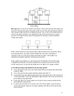
The monitor system usually can adopt the one-point ground.  


Please connect the ground end of 3-pin socket in the monitor system to the ground port of 

the system (protection ground cable) 


4. The shortcut way to check the electric system using the digital multimeter


For 220V AC socket, from the top to the bottom, E (ground cable), N (neutral cable), L(live cable). 

Please refer to the following figure.  


There is a shortcut way to check these thee cables connection are standard or not (not the 

accurate check).  

Importance 

In the following operations, the multimeter range shall be at 750V! 


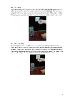
For E (earth cable) 

Turn the digital multi-meter to 750V AC, use your one hand to hold the metal end, and then the 

other hand insert the pen to the E port of the socket. See the following figure. If the multi-meter 

shows 0, then you can see current earth cable connection is standard.  If the value is more than 

10, then you can see there is inductive current and the earth cable connection is not proper.  


Summary of Contents for X101VS

Page 1: ...i X101VS NVS User s Manual Version 1 2 0 ...

Page 2: ...ple 12 2 3 1 Network system 12 2 3 2 HDD backup series 13 2 4 Mouse Control 13 3 INSTALLATION AND CONNECTIONS 15 3 1 Check Unpacked NVS 15 3 2 About Front Panel and Real Panel 15 3 3 HDD Installation 15 3 4 Connecting Power Supply 16 3 5 Connecting Video Input and Output Devices 16 3 5 1 Connecting Video Input 16 3 5 2 Connecting Video Output 17 3 6 Connecting Audio Input Output Bidirectional Audi...

Page 3: ...4 1 Advanced Setup 23 4 5 Default 29 4 6 TV Adjust 30 5 WEB OPERATION 31 5 1 Network Connection 31 5 2 Login 31 5 2 1 Real time Monitor 34 5 2 2 PTZ 35 5 2 3 Color 38 5 2 4 Picture Path and Record Path 38 5 3 Configure 39 5 3 1 System Information 39 5 3 2 System Configuration 41 5 3 3 Advanced 55 5 3 4 Additional Function 61 5 4 Search 68 5 5 Alarm 72 5 6 About 72 5 7 Log out 73 5 8 Un install Web...

Page 4: ...ACKUP DEVICE LIST 81 APPENDIX C COMPATIBLE CD DVD DEVICE LIST 85 APPENDIX D COMPATIBLE DISPLAYER LIST 86 APPENDIX E COMPATIBLE SWITCHER LIST 87 APPENDIX F COMPATIBLE WIRELESS MOUSE LIST 88 APPENDIX G EARTHING 89 APPENDIX H TOXIC OR HAZARDOUS MATERIALS OR ELEMENTS 94 ...

Page 5: ...e tool for the installation and operation of your system Here you can find hardware installation cable connection information and general operations also here you can find web operation instruction Before installation and operation please read the following safeguards and warnings carefully ...

Page 6: ...ination and repair work should be done by the qualified service engineers We are not liable for any problems caused by unauthorized modifications or attempted repair 5 Environment The NVS should be installed in a cool dry place away from direct sunlight inflammable explosive substances and etc This series product shall be transported storage and used in the environment ranging from 0 to 55 6 Acces...

Page 7: ...arious areas such as banking telecommunication electric power interrogation transportation intelligent resident zone factory warehouse resources and water conservancy 1 2 Features This series product has the following features Real time monitor It has analog output port VGA port You can use monitor or displayer to realize surveillance function System supports TV VGA output at the same time Storage...

Page 8: ...nput NTSC PAL BNC 1 0VB P P B75Ω Video Output 1 ch PAL NTSC BNC 1 0VP P 75Ω composite video signal output 1 ch VGA output Support TV VGA video output at the same time Video Standard PAL 625 line 50f s NTSC 525 line 60f s Record Speed Real time Mode PAL 1f s to 25f s per channel and NTSC 1f s to 30f s per channel Video Partition 1 windows Optional 1 2 windows 1 4 windows Monitor Touring Resolution ...

Page 9: ...s control File download backup and playback Multiple devices share information via corresponding software such as PSS and DSS Network alarm input and output Bidirectional audio Motion Detection and Alarm Motion Detection Zone setup support 396 PAL 22 18 NTSC 22 15 detection zones Various sensitivity levels Alarm can activate record or external alarm or screen message prompt Video Loss Alarm can ac...

Page 10: ...ion HDD backup series Parameter 1 channel 2 channel 4 channel System Main Processor High performance industrial embedded micro controller OS Embedded LINUX System Resources Multiplex operations Multiple channel record multiple channel playback and network operation simultaneously Interface User friendly graphical user interface Input Devices USB mouse Input Method Arabic number English character d...

Page 11: ...screen though system is encoding normally Screen lock function to prevent unauthorized user seeing secret video Channel Information Channel name recording status screen lock status video loss status and motion detection status are shown on the bottom left of display screen Color Configuratio n Hue brightness contrast saturation and gain setup for each channel Audio Audio Input 1 ch 200 2000mv 10KΩ...

Page 12: ...rt various search engines such as time and type Version Display version information channel amount system version and release date On line user Display current on line user User Management User Manageme nt Multi lever user management various management modes Integrated management for local user serial port user and network user Configurable user power Support user group and its corresponding right...

Page 13: ...7 Installation Mode Desktop installation ...

Page 14: ... network status indication light Green Wireless internet in normal connection always on Wireless internet in unusual connection off ALM Alarm status indication light Red Armed always on Alarm data in transmission flickers Disarmed off Video Video transmission record status indication light Blue Video in normal transmission on In recording flickers No video in transmission off RS232 232 debug COM T...

Page 15: ...roper Power status indication light The red light is on when the power connection is proper HDD status indication light The red light is on when the HDD malfunction occurred 2 2 Rear Panel 2 2 1 SD backup series 1ch Figure 2 3 Name Connector Function V IN Video input port BNC Receive analog video signals from camera dome and other front end devices V OUT Video input port BNC Video output port Outp...

Page 16: ... Ethernet interface 12VDC Input 12V DC When supply power via PoE the power of cameras shall be less than 3W 2ch 4ch Figure 2 4 Port Name Connector Function AVIN Audio input port BNC 1 4 ch audio input port to receive analog audio signals from microphone Audio input port BNC 1 4 ch video input port to receive analog video signals from camera dome and other front end devices Video input port BNC Vid...

Page 17: ...t port BNC 1 4 ch audio input port to receive analog audio signals from microphone The first channel audio input also used as the audio talk input port VIDEO IN 1 4 Video input port BNC 1 4 ch video input port to receive analog video signals from camera dome and other front end devices AUDIO OUT 1 Audio output port BNC Audio output port Output analog audio signal to the devices such as sound box V...

Page 18: ... the cable A You can connect to the control devices such as speed dome PTZ B RS485_B It is the cable B You can connect to the control devices such as speed dome PTZ ANT Antenna Port To connect wireless antenna in order to receive 3G wireless signal Power input port Input 12V DC Power Button Power on off button When connect the Ethernet port please use crossover cable to connect the PC and use the ...

Page 19: ...word input dialogue box if you have not logged in In real time monitor mode you can go to the main menu When you have selected one menu item left click mouse to view menu content Implement the control operation Modify checkbox or motion detection status Click combo box to pop up drop down list ...

Page 20: ...eration such as double click one item in the file list to playback the video In multiple window mode double left click one channel to view in full window Double left click current video again to go back to previous multiple window mode Right click mouse In real time monitor mode pops up shortcut menu one window four window Pan Tilt Zoom color setting search record main menu Among which Pan Tilt Zo...

Page 21: ...l and the ports in the rear panel please refer to the appendix for detailed information The model in the front panel is very important please check according to your purchase order The label in the rear panel is very important too Usually we need you to represent the serial number when we provide the service after sales 3 3 HDD Installation This series NVS has only one SATA HDD Please use HDD of 7...

Page 22: ...table lightness Guarantee the stability and reliability of the camera signal The camera shall be installed in a cool dry place away from direct sunlight inflammable explosive substances and etc The camera and the NVS should have the same grounding to ensure the normal operation of the camera Guarantee stability and reliability of the transmission lineBTTTB Please use high quality sound shielded BN...

Page 23: ...tional Audio 3 6 1 Audio Input These series products adopt BNC port Due to high impedance of audio input please use active sound pick up Audio transmission is similar to video transmission Try to avoid interference dry joint loose contact and it shall be away from high tension current 3 6 2 Audio Output The audio output signal parameter is usually over 200mv 1KΩ BNC It can directly connect to low ...

Page 24: ...stem consists of four accounts Username admin Password admin administrator local and network Username 888888 Password 888888 administrator local only Username 666666 Passwords 666666 Lower authority user who can only monitor backup and etc Username default Password default hidden user You can use USB mouse front panel or keyboard to input About input method Click to switch between numeral English ...

Page 25: ...e left top corner of the preview interface you can see the preview zoom button See Figure 4 2 Left click the icon you can see a hook icon Now you have enabled the preview zoom function You can drag the mouse to zoom in the image Figure 4 2 4 2 2 Live Viewing After you logged in the system is in live viewing mode You can see system date time and channel name 1 Recording status 3 Video loss 2 Motion...

Page 26: ...in Figure 4 4 Cover area Privacy mask Here is for you to set privacy mask section You can drag you mouse to set proper section size In one channel video system max supports 4 zones Preview monitor privacy mask has two types Preview and Monitor Preview means the privacy mask zone can not be viewed by user when system is in preview status Monitor means the privacy mask zone can not be view by the us...

Page 27: ...ot mode size quality and frequency See Figure 4 5 Figure 4 5 4 3 1 2 Activation Snapshot In Encode interface click snapshot button to input snapshot mode size quality and frequency See Figure 4 6 After you enabled this function system can snapshot when the corresponding alarm occurred Figure 4 6 4 3 1 3 Priority ...

Page 28: ... as zero You need to disable DHCP function to view current IP information Besides when PPPoE is operating you can not modify IP Subnet mask Gateway TCP port Default value is 37777 You can modify if necessary UDP port Default value is 37778 You can modify if necessary HTTP port Default value is 80 Max connection system support maximal 20 users 0 means there is no connection limit Preferred DNS DNS ...

Page 29: ... 1 1 IP Filter IP filter interface is shown as in Figure 4 9 You can add IP in the following list The list supports max 64 IP addresses Please note after you enabled this function only the IP listed below can access current NVS If you disable this function all IP addresses can access current NVS Figure 4 9 4 4 1 2 Multiple Cast Setup Multiple cast setup interface is shown as in Figure 4 10 Figure ...

Page 30: ...et transmission Used for multiple cast broadcast in limited space Except the above mentioned addresses of special meaning you can use other addresses For example Multiple cast IP 235 8 8 36 Multiple cast PORT 3666 After you logged in the Web the Web can automatically get multiple cast address and add it to the multiple cast groups You can enable real time monitor function to view the view Please n...

Page 31: ...New Deli GMT 5 Bangkok GMT 7 Beijing Hong Kong GMT 8 Tokyo GMT 9 Sydney GMT 10 Hawaii GMT 10 Alaska GMT 9 Pacific Time P T GMT 8 American Mountain Time M T GMT 7 American Central Time C T GMT 6 American Eastern Time E T GMT 5 Atlantic Time GMT 4 Brazil GMT 3 Middle Atlantic Time GMT 2 Figure 4 12 4 4 1 5 DDNS Setup DDNS setup interface is shown as in Figure 4 13 You need a PC of fixed IP in the in...

Page 32: ...English character and Arabic number Max 32 digit Receiver Please input receiver email address here System max supports 3 email boxes SSL enable System supports SSL encryption box Interval The send interval ranges from 0 to 3600 seconds 0 means there is no interval Health email enable Please check the box here to enable this function This function allows the system to send out the test email to che...

Page 33: ...m Serv U FTP Server Serv U Administator Now you can set user password and FTP folder Please note you need to grant write right to FTP upload user See Figure 4 15 Figure 4 15 You can use a PC or FTP login tool to test setup is right or not For example you can login user ZHY to H140H 140H 140HTUFTP 10 10 7 7UTH and then test it can modify or delete folder or not See Figure 4 16 ...

Page 34: ...h is upload file length When setup is larger than the actual file length system will upload the whole file When setup here is smaller than the actual file length system only uploads the set length and auto ignore the left section When interval value is 0 system uploads all corresponding files After completed channel and weekday setup you can set two periods for one each channel 4 4 1 8 3G Setup Th...

Page 35: ...ops up a dialogue box You can highlight to restore default factory setup See Figure 4 19 Select all General Encode Schedule RS232 Network Alarm Detect Pan tilt zoom Channel name Please highlight icon to select the corresponding function After all the setups please click save button system goes back to the previous menu Warning System menu color date and time user account will not maintain previous...

Page 36: ...4 19 4 6 TV Adjust Here is for you to adjust TV output setup See Figure 4 20 Please drag slide bar to adjust each item After all the setups please click OK button system goes back to the previous menu Figure 4 20 ...

Page 37: ...atest web control and the new version can overwrite the previous one If you want to un install the web control please run uninstall webrec2 0 bat Or you can go to C Program Files webrec to remove single folder Please note before you un install please close all web pages otherwise the un installation might result in error 5 2 Login Open IE and input NVS address in the address column For example if ...

Page 38: ...ion the interface is shown as below See Figure 5 3 Please input your user name and password Default factory name is admin and password is admin Note For security reasons please modify your password after you first login Figure 5 3 ...

Page 39: ...Please note current preview window is circled by a green rectangle zone Section 5 Here you can view window switch button You can also select video priority between fluency or real time System monitor window switch supports full screen 1 window 4 window 6 window 8 window 9 window 13 window 16 window 20 window 25 window 36 window See Figure 5 4 Figure 5 4 Preview window switch System support 1 4 8 9...

Page 40: ...hen you click local record button the system begins recording and this button becomes highlighted You can go to system folder RecordDownload to view the recorded file 4 Capture picture You can snapshoot important video All images are memorized in system client folder download picture default 5 Audio Turn on or off audio It has no relationship with system audio setup 6 Close video Please refer to F...

Page 41: ... audio data from the 1 channel Local Play The Web can playback the saved Extension name is dav files in the PC end Click local play button system pops up the following interface for you to select local play file See Figure 5 10 Figure 5 10 5 2 2 PTZ Before PTZ operation please make sure you have properly set PTZ protocol Click PTZ button the interface is shown as in Figure 5 11 ...

Page 42: ...ust section size It can realize PTZ automatically 5 2 2 2 Speed System supports eight level speed You can select from the dropdown list Speed 2 is faster than speed 1 5 2 2 3 Zoom Focus Iris Here is a sheet for you reference Name Function key Function Function key Function Zoom Near Far Focus Near Far Iris close Open In Figure 5 11 click PTZ setup button you can see the following interface See Fig...

Page 43: ...n X441H441H441HFigure 5 12X move the camera to your desired location and then input preset value Click add button you have set one preset 5 2 2 7 Auto tour In X442H442H442HFigure 5 12 input auto tour value and preset value Click add button you have added one preset in the tour Repeat the above procedures you can add more presets in one tour 5 2 2 8 Assistant You can select the assistant item from ...

Page 44: ...lect one channel and then adjust its brightness contrast hue and saturation Current channel border becomes green Or you can click default button to use system default setup Figure 5 14 5 2 4 Picture Path and Record Path Click more button in Figure 5 14X you can see an interface is shown as in Figure 5 15 Figure 5 15 ...

Page 45: ...Please click choose button to modify path Figure 5 17 Click reboot button system pops up the following dialogue box See Figure 5 18 Please click OK to reboot Figure 5 18 If there is local use logged in the system menu or the Web logged in user has no right to reboot the device system pops up a dialogue box to alert you 5 3 Configure 5 3 1 System Information 5 3 1 1 Version Information Here you can...

Page 46: ...40 Figure 5 19 5 3 1 2 HDD information Here you can view local storage status free capacity and total capacity See Figure 5 20 Figure 5 20 5 3 1 3 Log Here you can view system log See Figure 5 21 ...

Page 47: ...nt log clear and file operation Search You can select log type from the drop down list and then click search button to view the list Clear You can click this button to delete all displayed log files Please note system does not support clear by type Backup You can click this button to backup log files to current PC 5 3 2 System Configuration Please click save button to save your current setup 5 3 2...

Page 48: ... is full now system stops record If current working HDD is full now system goes to overwrite the previous file Pack Duration Here you can select file size The value ranges from 1 to 120 Default setup is 60 minutes Device No When you are using one remote control not included in the accessory bag to manage multiple devices you can give a serial numbers to the device Please current series product doe...

Page 49: ...43 Figure 5 24 Figure 5 25 Figure 5 26 Figure 5 27 ...

Page 50: ... value is null in VBR mode Please refer to recommend bit rate for the detailed information Recommended Bit Recommended bit rate value according to the resolution and frame rate you have set Color Setting Here you can set video brightness contrast ness hue saturation and gain The value ranges from 0 to 100 Default value is 50 Please note some series devices do not support OSD transparent setup func...

Page 51: ...ck save button Refresh Click this button to get device latest configuration information Click copy interface the interface is shown as in Figure 5 28 If you have completed the setup for channel 1 you can click 3 to copy current setup to channel 3 Or you can click 2 3 and 4 to copy current setup to channel 2 channel 3 and channel 4 Figure 5 28 5 3 2 3 Schedule Here you can set different periods for...

Page 52: ... motion detection snapshot and alarm snapshot Please select date Current setup applies to current day by default You can draw a circle before the week to apply the setup to the whole week After complete setup please go back to X459H 459H 459HFigure 5 29X and then click save to save current time period setup Copy It is a shortcut menu button You can copy current channel setup to one or more all cha...

Page 53: ...ard first DHCP Dynamically get IP address You can get the device IP from the DHCP server if you enabled this function TCP Port Default value is 37777 You can modify if necessary HTTP Port Default value is 80 Email The email interface is shown as in Figure 5 32 Figure 5 32 Please refer to the following sheet for detailed information ...

Page 54: ... addresses DDNS The DDNS interface is shown as in Figure 5 33 Please make sure your NVS support this function Figure 5 33 Please refer to the following sheet for detailed information Parameter Function Server Type You can select DDNS protocol from the dropdown list and then enable DDNS function The private DDNS protocol means you use your self defined private protocol to realize DDNS function Serv...

Page 55: ... Server IP Input remote storage server IP address Port Input Remote storage server port number User Name Log in user account File length The file length you upload to the FTP When setup is larger than the actual file length system will upload the whole file When setup here is smaller than the actual file length system only uploads the set length and auto ignore the left section When interval value...

Page 56: ...only and its port shall be 123 The update interval ranges from 1 to 65535 Default value is 10 minutes Figure 5 35 You can refer to the following sheet for time zone information City Region Name Time Zone London GMT 0 Berlin GMT 1 Cairo GMT 2 Moscow GMT 3 New Deli GMT 5 Bangkok GMT 7 Beijing Hong Kong GMT 8 Tokyo GMT 9 Sydney GMT 10 Hawaii GMT 10 Alaska GMT 9 Pacific Time P T GMT 8 American Mountai...

Page 57: ...s in Figure 5 37 Multiple cast Please refer to chapter 4 4 1 2 for detailed multiple cast setup information PPPoE Please input the PPPoE user name and password you get from the IPS internet service provider and enable PPPoE function Please save current setup and then reboot the device to get the setup activated Device connects to the internet via PPPoE after reboot You can get the IP address in th...

Page 58: ...7 5 3 2 5 Detect Analysis the video system enable motion detection alarm when it detects the motion signal reached the specified sensitivity The detection interface is shown as in Figure 5 38 Figure 5 38 Figure 5 39 ...

Page 59: ...period The value ranges from 0s to 15s Alarm latch System can delay the alarm output for specified time after alarm ended The default value is 10s Alarm upload System can upload the alarm signal to the centre Including alarm centre Record channel System auto activates motion detection channel multiple choices to record once alarm occurs working with motion detection function Please note you need t...

Page 60: ...aud rate Default setup is 9600 Data Bit Default setup is 8 Please set according to the speed dome dial switch setup Stop bit Default setup is 1 Please set according to the speed dome dial switch setup Parity Default setup is none Please set according to the speed dome dial switch setup Save You can click save button after you complete setup for one channel or you can complete the whole setups and ...

Page 61: ... Import configuration from PC to the system 5 3 3 Advanced 5 3 3 1 HDD Management HDD management includes net storage management and local storage management Please note if you want to use local storage function your storage device need to support current function Please select the storage device first and then you can see the items on your right become valid You can check the corresponding item h...

Page 62: ...ion Format Clear data in the disk Read write Set current SD card as read write Read only Set current card as read Recover Recover dada after error occurs Please note system needs to reboot to activate current setup 5 3 3 2 Record Record control interface is shown as in Figure 5 43 Figure 5 43 ...

Page 63: ...er what period applied in the record setup 5 3 3 3 Account Here you can add remove user or modify password See Figure 5 44 Figure 5 44 5 3 3 3 1 Modify Password Click password button the interface is shown as in Figure 5 45 Here you can modify account password Please select the account from the dropdown list input the old password and then input the new password twice Click the Save button to conf...

Page 64: ...put output setup system setup log view clear log upgrade system control device and etc The modify group interface is similar to the Figure 5 46 Figure 5 46 5 3 3 3 3 Add Modify User Click add user button the interface is shown as in Figure 5 47 Please input the user name password select the group it belongs to from the dropdown list Then you can check the corresponding rights for current user For ...

Page 65: ... 5 47 5 3 3 4 Auto Maintenance Here you can select auto reboot and auto delete old files interval from the dropdown list See Figure 5 48 Figure 5 48 5 3 3 5 Snapshot Snapshot interface is shown as in Figure 5 49 ...

Page 66: ...Frame rate You can select from the dropdown list The value ranges from 1f s to 7f s Resolution You can select from the dropdown list There are two options CIF QCIF Quality You can select from the dropdown list Here is for you to set video quality There are six options 10 30 50 60 80 100 100 is the best quality 5 3 3 6 Abnormity The abnormity interface is shown as below See Figure 5 50 ...

Page 67: ...ed time after alarm stops Then system disables alarm and corresponding activation output The default value is 10s Send email If you enable this function system can send out email to alarm the specified user Alarm upload System can upload the alarm signal to the network includes the alarm centre Show message System can display alarm information in local NVS screen 5 3 4 Additional Function 5 3 4 1 ...

Page 68: ... Device management server number IP Device management server IP address Port Server port number Device ID Device ID in the device management server 5 3 4 2 Preferred DNS Here you can set server or local operator DNS address See Figure 5 52 This function is useful when you input domain name in some item Otherwise system can not parse the domain name ...

Page 69: ...63 Figure 5 52 5 3 4 3 CDMA GPRS The CDMA GPRS interface is shown as below See Figure 5 53 Figure 5 53 CDMA GPRS ...

Page 70: ... network Keep alive time You can set dialup duration Default value is 30s Period Click set button the interface is shown as in Figure 5 54 You can set the period to connect to the 3G network System only enables wireless network dialup function during the specified period There are max six periods in one day Wireless network status Login status You can see device has registered to the 3G network or...

Page 71: ...ick this button to save current setup Refresh Click this button to get device latest configuration 5 3 4 4 Mobile Configuration Mobile configuration interface is shown as in Figure 5 55 Figure 5 55 Mobile Configuration Please refer to the following sheet for detail information Parameter Function Send event message Device can send the event message alarm information motion detection and etc to the ...

Page 72: ...nect to the 3G network and you have enabled the 3G function When the specified mobile number sends out the message on to the device the device begins 3G dial up and then connect to the 3G network When the specified mobile number sends out the message off to the device the device disconnects the network and then becomes offline Dial save System can save the mobile phone number which can dial the de...

Page 73: ...onnect Note When the Auto connect function is enabled device will connect again automatically within a short time Please disable Auto connect function and click Save button first and then click the Disconnect button to terminate connection IP address It is the IP address after the device successfully connected to the wireless router Save Click this button to save current setup Refresh Click this b...

Page 74: ...Click search button you can see an interface is shown as in Figure 5 58 Please select record playback mode and then select start time end time and channel Then please click search button you can see the corresponding files in the list ...

Page 75: ... Figure 5 59 and then you can specify file name and path to download the file s to your local pc Figure 5 59 Now you can see system begins download and the download button becomes stop button You can click it to terminate current operation At the bottom of the interface there is a process bar for your reference See Figure 5 60 ...

Page 76: ...70 Figure 5 60 When download completed you can see a dialogue box shown as in Figure 5 61 Please click OK to exit Figure 5 61 ...

Page 77: ...e Download by file Select the file s and then click download button Download by time Download the recorded file s within your specified period Download Select the file you need multiple choices and then click download button you can see system pops up a dialogue box See Figure 5 59 Input the downloaded file name specify the path and then click OK button You can see system begins download and the d...

Page 78: ...re 5 63 Here you can set device alarm type and alarm sound setup Please make sure your device has enabled the alarm upload function Figure 5 63 5 6 About Click about button you can view current web information See Figure 5 64 Playback device IP address and channel number Playback control bar ...

Page 79: ...e 5 65 You need to input user name and password to login again Figure 5 65 5 8 Un install Web Control You can use web un install tool uninstall web bat to un install web control Please note before you un installation please close all web pages otherwise the un installation might result in error ...

Page 80: ...74 6 Professional Surveillance System Besides Web you can use our Professional Surveillance Software PSS to login the device For detailed information please refer to PSS user s manual ...

Page 81: ...environment is too harsh too much dust Hardware malfunction 3 System cannot detect hard disk There are following possibilities HDD is broken HDD ribbon is damaged HDD cable connection is loose Main board SATA port is broken 4 There is no video output whether it is one channel multiple channel or all channel output There are following possibilities Program is not compatible Please upgrade to the la...

Page 82: ... input Playback is not continuous when the screen is blue 9 Time display is not correct There are following possibilities Setup is not correct Battery contact is not correct or voltage is too low Crystal is broken 10 NVS cannot control PTZ There are following possibilities Front panel PTZ error PTZ decoder setup connection or installation is not correct Cable connection is not correct PTZ setup is...

Page 83: ...ies Network fluency is not good Client end resources are limit There is multiple cast group setup in NVS This mode can result in mosaic Usually we do not recommend this mode There is privacy mask or channel protection setup Current user has no right to monitor NVS local video output quality is not good 14 Network connection is not stable There are following possibilities Network is not stable IP a...

Page 84: ...e cannot connect to the wireless IP of the device There are following possibilities There are too many wireless routers and the frequency band setup are the same Please set the frequency band first Device wire IP and wireless IP address are in the same IP segment Daily Maintenance Please use the brush to clean the board socket connector and the chassis regularly The device shall be soundly earthed...

Page 85: ...ularly After recording stops please wait 15 seconds before removing the SD card in order to ensure its data completeness Please do not set the SD card as the storage medium of scheduled recording or it will shorten its life span and get damaged ...

Page 86: ... capacity i m which is storage of each channel needed unit Mbyte i m i q i h i D 2 In the formula i h means the recording time for each day hour i D means number of days for which the video shall be kept Step 3 According to Formula 3 to calculate total capacity accumulation T q that is needed for all channels in the NVS during scheduled video recording c i i T m q 1 3 In the formula c means total ...

Page 87: ... Kingston DataTraveler 2G Maxell USB Flash Stick 128M Maxell USB Flash Stick 256M Maxell USB Flash Stick 512M Maxell USB Flash Stick 1G Maxell USB Flash Stick 2G Kingax Super Stick 128M Kingax Super Stick 256M Kingax Super Stick 512M Kingax Super Stick 1G Kingax Super Stick 2G Netac U210 128M Netac U210 256M Netac U210 512M Netac U210 1G Netac U210 2G Netac U208 4G Teclast Ti Cool 128M Teclast Ti ...

Page 88: ...15HBK 00 1 5TB Seagate FreeAgent Go ST905003F 500GB Aigo H8169 500GB Compatible USB DVD Burner List NOTE Please upgrade the NVS firmware to latest version to ensure the accuracy of the table below And you can use the USB cable with the model recommended to set USB burner Manufacturer Model Sony DRX S70U Benq TW200D Compatible SATA DVD Burner List NOTE Please upgrade the NVS firmware to latest vers...

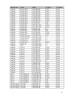
Page 89: ...te Pipeline HD 2 ST3320311CS 320G SATA Seagate Barracuda ST31000340AS 1T SATA Seagate ES 2 ST31000340AS 1T SATA Seagate SV35 2 ST3160815SV 160G SATA Seagate SV35 2 ST3250310SV 250G SATA Seagate SV35 2 ST3320620SV 320G SATA Seagate SV35 2 ST3500320SV 500G SATA Seagate SV35 2 ST3750640SV 750G SATA Seagate SV35 2 ST3320320SV 320G SATA Seagate SV35 2 ST3500630SV 500G SATA Seagate SV35 3 ST31000340SV 1...

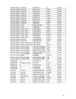
Page 90: ...eries WD7500AYYS 750G SATA Western Digital Caviar Green series WD20EADS 2T SATA Western Digital Caviar Green series WD15EADS 1 5TB SATA Western Digital Western Digital WD10EVVS 63M5BO 1TB SATA Western Digital Western Digital WD20EVDS 63T3B0 2TB SATA Western Digital Western Digital WD15EVDS 63V9B0 1 5TB SATA Western Digital Western Digital WD10EVVSWDV GP 1TB SATA Western Digital Western Digital ser...

Page 91: ...uracy of the table below And you can use the USB cable with the model recommended to set USB burner Manufacturer Model Port Type Type Sony DRX S50U USB DVD RW Sony DRX S70U USB DVD RW Sony AW G170S SATA DVD RW Samsung TS H653A SATA DVD RW Panasonic SW 9588 C SATA DVD RW Sony DRX S50U USB DVD RW BenQ 5232WI USB DVD RW ...

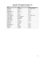
Page 92: ... Q7T4 17 inch SANGSUNG LCD SMT 1922P 19 inch BENQ LCD Q7T3 17 inch LENOVO LCD LXB L17C 17 inch SANGSUNG LCD 225BW 22 inch wide screen LENOVO CRT LXB FD17069HB 17 inch LENOVO CRT LXB HF769A 17 inch LENOVO CRT LX GJ556D 17 inch SAMSUNG LCD T190 19 inch PHILIPS LCD HWC9190I 20 inch BENQ LCD ET 0021 B DELL LCD E1909Wf 19 inch SANGSUNG LCD T240 24 inch DELL LCD E170Sc 17 inch BENQ LCD G2219HD 19 inch L...

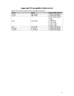
Page 93: ...l Network Working Mode D LinK DES 1016D 10 100M self adaptive D LinK DES 1008D 10 100M self adaptive Ruijie RG S1926S There are five network modes 1 AUTO 2 HALF 10M 3 FULL 10M 4 HALF 100M 5 FULL 100M H3C H3C S1024 10 100M self adaptive TP LINK TL SF1016 10 100M self adaptive TP LINK TL SF1008 10 100M self adaptive ...

Page 94: ...88 Appendix F Compatible Wireless Mouse List Please refer to the following sheet for compatible SD card brand Brand Model V80 Rapoo 3500 Logitech M215 Shuangfeiyan Tianyao G7 630 ...

Page 95: ...t emphasizing the all round protection including building transmission cable device ground and etc There shall be comprehensive management and the measures shall be scientific reliable practical and economic Considering the high voltage during the inductive thundering the International Electrotechnical Committee IEC standard on the energy absorbing step by step theory and magnitude classification ...

Page 96: ...as many modes but the selection depends on the system structure and performance The following are some successfully experience from our past work One point ground In the following figure you can see there is a one point ground This connection provides common port to allow signal to be transmitted in many circuits If there is no common port the error signal transmission occurred In the one point gr...

Page 97: ...onsidering the earthing you need to think about two aspects The first is the system compatibility and the other is the external interference coupling into the earth circuit which results in system error For the external interference is not regular it is not easy to resolve 3 Thunder proof ground method in the monitor system The monitor system shall have sound thunder proof earthing to guarantee pe...

Page 98: ... figure There is a shortcut way to check these thee cables connection are standard or not not the accurate check Importance In the following operations the multimeter range shall be at 750V For E earth cable Turn the digital multi meter to 750V AC use your one hand to hold the metal end and then the other hand insert the pen to the E port of the socket See the following figure If the multi meter s...

Page 99: ...le connection is not proper or it is not the live cable at all For N Neutral cable Turn the digital multi meter to 750V AC use your one hand to hold the metal end and then the other hand insert the pen to the N port of the socket See the following figure If the multi meter shows 0 then you can see current N cable connection is standard If the value is more than 10 then you can see there is inducti...

Page 100: ...od the toxic or hazardous substance or elements contained in products will not leak or mutate so that the use of these substances or elements will not result in any severe environmental pollution any bodily injury or damage to any assets The consumer is not authorized to process such kind of substances or elements please return to the corresponding local authorities to process according to your lo...

Reviews: