background image


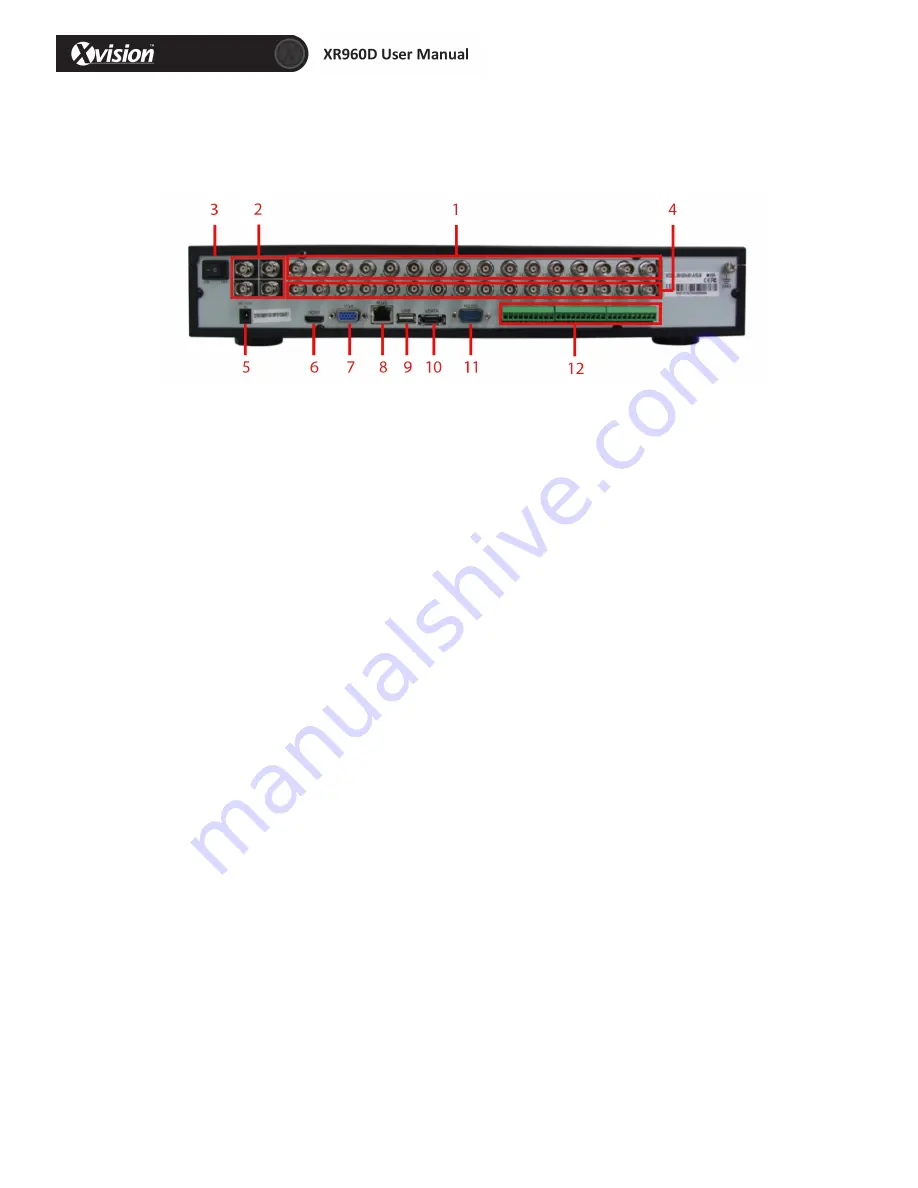
16   Channel   DVR   –   Back   Panel   


16   Channel   back   panel   definition   
   

1.


Video   Input

:   Connect   CH1-­‐16   

2.


Audio   Out/Video   Out

:   Connect   to   Monitor   (Video   BNC),   Audio   out   RCA   Interface   

3.


Power   Switch

:   Turn   power   on   or   off   

4.


Audio   In

:   16   Channel   Audio   Input   

5.


Power   Port

:   Connect   power   supply   –   DC12V       

6.


HDMI   Port

:   Connect   HDMI   Cable   

7.


VGA   Port

:   Connect   VGA   Monitor   

8.


Ethernet   Port

:   Connect   LAN,   Ethernet   (RJ45   Interface)   

9.


USB   Port

:   Connect   USB   Device   

10.


eSATA   Port

:   Connect   external   Hard   Drive   

11.


RS232   Port

:   RS232   Output   

12.


Alarm    in/NO/COM

:    IO    alarm    input    of    DVR.    For    NO    COM    alarm    output    of    DVR   

(there   are   two   state   of   alarm   type,   NO/NC)   


Summary of Contents for Professional XR960D4

Page 1: ... Channel User Manual Version 1 HD 960H Thank you purchasing the XR960 DVR from Xvision Please ensure that you read and understand this User Guide before operating the DVR Please store this User Guide in an easily accessible location ...

Page 2: ...cord Setup 13 3 8 HDD Setup 14 3 9 User of Taskbar 15 4 Operating System 17 4 1 User Login 17 4 2 Basic 18 4 2 1 System Setup 18 4 2 2 Date Time 19 4 2 3 Display 20 4 2 4 Record 20 4 3 Advance 23 4 3 1 Alarm 23 4 3 2 Network 31 4 3 3 Networking 34 4 3 4 PTZ 36 4 4 Search 36 4 5 HDD 37 4 6 System Information 38 4 6 1 Device Information 38 4 6 2 Network 38 4 6 3 Online User 39 4 6 4 Record Informati...

Page 3: ...1 Installation 1 1 Contents Before starting up the DVR please make sure you have all of the following contents Or DVR 1x DVR Power Supply 1x Remote Control Software CD User Manual Pack of Mounting Screws ...

Page 4: ...to channel 4 channel 5 to channel 8 next etc 3 Direction OK button Control left right up down of menu items and click the ok button 4 Menu Esc Open DVR menu or Exit 5 Power DVR sleep wake up button 4 Channel DVR Back Panel 4 Channel back panel definition 1 Video Input Connect CH1 4 2 Audio Out Video Out Connect to Monitor Video BNC Audio out RCA Interface 3 Ethernet Port Connect LAN Ethernet RJ45 ...

Page 5: ...put or ground connection and IO alarm 8 Channel DVR Front Panel Front Panel Definition 1 Number Button Select channel or input number where needed 2 Record Button Start Stop recording 3 Multi screen camera display button 4 Pause Frame play button 5 Play Slow play button 6 Exit Button 7 Menu Button 8 Jog Shuttle 9 On Screen menu navigation keys 10 Power On Off 11 USB Port 8 Channel DVR Back Panel ...

Page 6: ... LAN Ethernet RJ45 Interface 9 USB Port Connect USB Device 10 eSATA Port Connect external Hard Drive 11 RS232 Port RS232 Output 12 GND COM NO Alarm input output for ground connection and IO alarm 16 Channel DVR Front Panel Front Panel Definition 1 Number Button Select channel or input number where needed 2 Record Button Start Stop recording 3 Multi screen camera display button 4 Pause Frame play b...

Page 7: ...f 4 Audio In 16 Channel Audio Input 5 Power Port Connect power supply DC12V 6 HDMI Port Connect HDMI Cable 7 VGA Port Connect VGA Monitor 8 Ethernet Port Connect LAN Ethernet RJ45 Interface 9 USB Port Connect USB Device 10 eSATA Port Connect external Hard Drive 11 RS232 Port RS232 Output 12 Alarm in NO COM IO alarm input of DVR For NO COM alarm output of DVR there are two state of alarm type NO NC...

Page 8: ...tallation Before turning on the DVR please install the HHD Firstly check whether SATA installed or not before installation SATA installation number differs for different models To install HDD follow the below steps ...

Page 9: ...tem startup Power on off Connect the power plug to the power port on the back of the DVR The system will automatically run a status check and will start after few seconds You will see a wizard interface after the system loading ...

Page 10: ...ase login to the main menu and setup to complete this function 3 1 Wizard interface Wizard interface is shown below We recommend the initial user finishes the guide step by step for the basic settings 3 2 Administrator Login Interface Here we recommend you setup a password for administrator and then click Next for more settings if you click Cancel you will enter directly into the Main Menu if you ...

Page 11: ...e format types MM DD YYYY DD MM YYYY and YYYY MM DD Time Format 24 hour 12 hour Time Zone Click the down arrow time zone options will be displayed please select your time zone Please Note Once the DVR connects with the internet it will automatically adjust the time to the time zone you have chosen Please make sure the time zone you chosen is the desired local time zone Camera System PAL NTSC optio...

Page 12: ... page to correct the settings and then click Next If no testing is required just click Skip to go to the next page as displayed below 3 6 DDNS Port Setup DDNS Enable Disable please enable the DDNS to use a domain name server Server Choose your domain name server 3322 dyndns no IP changeip or dnsexit Host Name Enter the host name you registered on the domain name server User Name Enter the user nam...

Page 13: ...ld like change the web port change to 8088 when you need to access through the browser you will need to add the web port after the IP address Please Note the port range is 1 65535 some local ISP s may block port 80 3 7 Record Mode Record Setup Set up recording and audio for each channel There are two record modes Always Schedule For ease setup one channel and then copy to the others as shown on th...

Page 14: ...nstalled HDD must be formatted before using the DVR Overwrite There are three options to choose from by days by capacity and never After the set up of the disk the save and confirm interface will be shown on screen and click Save to log out After the completion of setup wizard the DVR can work properly If personalized settings are needed you can login to the menu to setup ...

Page 15: ...to show the channel to be displayed 3 Display of quad Click to display 4 channels in sequence 4 Display of 8 channels Click to display 8 channels in sequence 5 Settings of colour Open colour setup interface As shown on the following page Choose the channel to be viewed BRI CON HUE SAT can be adjusted from 1 63 Click default to recover to default settings Click apply to save the settings 6 PIP Drag...

Page 16: ...9 zoom focus and iris of PTZ can be adjusted Select the code of preset point 3 Setup of preset point choose the channel to set the preset point 4 Cruise line click cruise setup to add or delete cruise 8 Volume adjusts Open volume adjust control bar 9 Manual record settings open close manual record 10 Video query Open video query interface and view the video 11 Right click any position on the scree...

Page 17: ...now need to input your password here Enter the menu the icon will be highlighted when the cursor moves onto the icon click to enter 1 Basic Open the basic menu and 5 functions show in interface system setup time date setup record setup display setup and user configuration 2 Advance Open the advance menu you can set up the alarm network settings Internet application settings and PTZ configuration 3...

Page 18: ...o format VGA resolution language logout time and startup wizard Device name Change the device name click the input box and the keyboard will pop up Click the keyboard to edit the device name Device ID Change the device ID click the input box and the keyboard will pop up Click the keyboard to edit the device name Select PAL or NTSC from the drop down box VGA resolution Adjust according to the VGA u...

Page 19: ...unction Time sever Select the proof sever among multi sever address from the drop down box Please Note After setting is completed click Apply to finish setting and click Default To recover to default settings click Exit to return DST setup Enable Mark enables the use of the DST setup Mode Select Week or Date from the box Offset Time period ahead or delayed Select One hour or Two hours from the box...

Page 20: ...ss Contrast Hue and Saturation can be modified Click Apply to save Overlay Click Setting and select one CH Select Time overlay and Name overlay Click Default to cancel Copy CH Copy one CH setting to another CH 4 2 4 Record Basic setting CH Order of the DVR channel Enable Click to enable the basic setting Audio Click to enable audio recording Mode Click Always or Time recording to make the DVR reco...

Page 21: ...25 fps is for option NTSC 1 30 fps is for option Quality Best Better Good Normal for option Copy CH Copy one CH setting to another CH Schedule CH Order of the DVR channel Set the mode of recording Manual Normal Alarm Double click the recording schedule the schedule window will pop up You can set the recording schedule here ...

Page 22: ...User Create User Create a new User and configure authority 1 Basic information Fill in the User name Password Retype password User type Binding Client MAC MAC 2 Authority Select the Authority for this user ...

Page 23: ...or motion detection Red Area in red indicates there is moving object in the detecting area Green Area in green indicates there is no moving object in the detecting area Grey Area in grey indicates this is not the detecting area Alarm plan Click the alarm button to enable the alarm Drag your mouse to set your alarm plan Red area is the time with alarm Grey is the time without alarm Click Apply to s...

Page 24: ... when there is an alarm the DVR will send the snapped picture to the mailbox you set Alarm output Place a check mark This will trigger the external alarm Alarm output duration Click the inverted triangle options 10s 30s 1min 3 min 5min 10min 15min 30min Buzzer Click the inverted triangle options None 10s 30s 1min 3 min 5min 10min 15min 30min Pop out image Click the inverted triangle options None C...

Page 25: ...me for the sensor Schedule From Monday to Sunday 0 00 to 24 00 setup alarm for time periods time period cannot cross a day double click on the time to enter the time period setup None black colour background colour Alarm red colour Copy For ease setup one channel and then copy to the others Trigger The processing for alarming click settings display as below ...

Page 26: ... external alarm Alarm output duration Click the inverted triangle options 10s 30s 1min 3 min 5min 10min 15min 30min Buzzer Click the inverted triangle options None 10s 30s 1min 3 min 5min 10min 15min 30min Pop out image Click the inverted triangle options None CH1 CH2 Post record Click the inverted triangle options 10s 30s 1min 3 min 5min 10min 15min 30min Pre record Click the inverted triangle op...

Page 27: ...cture to the mailbox you set Alarm output Place a check mark will trigger the external alarm Alarm output duration Click the inverted triangle options 10s 30s 1min 3 min 5min 10min 15min 30min Buzzer Click the inverted triangle options None 10s 30s 1min 3 min 5min 10min 15min 30min Pop out image Click the inverted triangle options None CH1 CH2 Post record Click the inverted triangle options 10s 30...

Page 28: ...el sensitivity 1 2 3 Schedule From Monday to Sunday 0 00 to 24 00 setup of alarm for time periods time period cannot cross a day double click on the time to enter the time period setup None black colour background colour Alarm red colour Copy For ease setup one channel and then copy to the others Trigger The processing for alarming click settings ...

Page 29: ...et Alarm output Place a check mark This will trigger the external alarm Alarm output duration Click the inverted triangle options 10s 30s 1min 3 min 5min 10min 15min 30min Buzzer Click the inverted triangle options None 10s 30s 1min 3 min 5min 10min 15min 30min Pop out image Click the inverted triangle options None CH1 CH2 Post record Click the inverted triangle options 10s 30s 1min 3 min 5min 10m...

Page 30: ... will snap a picture Send E mail Place a check mark when there is an alarm the DVR will send the snapped picture to the mailbox you set Alarm output Place a check mark This will trigger the external alarm Alarm output duration Click the inverted triangle options 10s 30s 1min 3 min 5min 10min 15min 30min Buzzer Click the inverted triangle options None 10s 30s 1min 3 min 5min 10min 15min 30min Pop o...

Page 31: ...settings If there is no router in your network fill in the IP you get from your Internet Service Provider ISP If there is a router in your network make sure you have set the subnet mask and default gateway correctly 4 Obtain DNS server address automatically This will come from your router or DHCP server 5 Use the following DNS sever addresses Preferred DNS server fill in the DNS you get from your ...

Page 32: ...tart after clicking OK If the user name and password are correct the system will connect to the network via the PPPOE The IP address will be filled automatically Click Apply after setup to save Please Note Click Apply after setup 3G Choose enable option of 3G switch then fill in APN and Access number according to your Mobile SIM card service provider ...

Page 33: ...ort 2 Web Port Http port default 80 if you change the web port for example 8088 when you need to access through browser you will need to add the web port after the IP address E g http ip address 8088 Click Apply after setup to save Sub stream All the setup here is for network transfer CH All DVR channels Enable Place a check mark which means use sub stream for network transfer ...

Page 34: ... Enable Disable please enable the DDNS when you use domain name server Server Choose your domain name server 3322 dyndns no IP change ip or dnsexit Host name The host name you registered on the domain name server User name The user name you registered on the domain name server Password The password you registered on the domain name server Test After setup click Test to check connected or not Click...

Page 35: ...L TLS User name Input the sender s email address Password Input the sender s email password To Input the email address you want to receive the alarm snapshots CC Input the email address you want to copy to add a maximum of 4 email addresses Test Click Test system will send a test email to the receiver Click Apply after setup to save UPnP Enable Disable Enable UPnP when your router supports UPnP Cl...

Page 36: ...the main menu click Search as show below After entering the playback interface the DVR will automatically search current day s recording files and show in the right window If there is no recording the right window will be empty Calendar Green red date background means there is a recording that day grey background means there is no recording that day and blue back ground shows the date you have sel...

Page 37: ...uantity of selected recording files Search Click SEARCH and the right window will display the recording files Playback Click PLAYBACK to enter into playback interface The left side shows the calendar the right side displays the playback time zone Green colour means normal recording red colour means alarm recording and black colour back ground colour means no recording On the time line there is a t...

Page 38: ...ase select the desired method Click Apply after setup to save 4 6 System Information After entering the main menu move the cursor to INFORMATION and click it 4 6 1 Device Information Device Name The name given to the DVR Device ID The ID of DVR Serial NO Serial number of DVR Firmware Version The firmware version of DVR MAC MAC address of DVR 4 6 2 Network LAN Shows the network status IP ADD of LAN...

Page 39: ...39 ADSL Shows the network status IP address preferred DNS server and alternate DNS server 4 6 3 Online user Shows the online user name IP add log in time and connection statuses ...

Page 40: ...m Set an auto maintenance time or frequency Auto Maintain System auto maintenance 1 If the user selects Never in the drop down box the system won t start auto maintenance But manual maintenance can still be operated 2 If the user chooses every month then the date will be shown in drop box Set the date and time to auto maintenance 3 If the user chooses Every week in drop down box the seven days of ...

Page 41: ...scan the USB Drive and start the upgrade Don t pull out the USB drive during upgrading STANDBY Click to standby Reboot Click to reboot Note Click save to save the setting click default back to default settings 4 7 2 Settings Export settings Copy the device setting to a USB drive Import settings Copy the system setting to this device Load factory default Contains system setting display setting devi...

Page 42: ...he items above or clear it all 4 8 Logout Enter the main menu move cursor to LOGOUT icon and then click it The NOTE window will pop up if you are sure to logout just click Yes This will then lock the main menu the password is needed if you want to enter it again ...

Page 43: ...A CVBS Video Compression H 264 Recording Frame Rate WD1 25fps WCIF 25fps WHD1 25fps Recording Mode Always Schedule Alarm Motion Detection Record Mode Audio Video Mobile Phone Supports Android Phone iPhone iPad Blackberry HDD 1 HDD Up to 4 TB 4 HDD Up to 16TB 4 HDD Up to 16TB eSATA N A Supports Supports Network Protocol IE PPPoE DDNS DHCP Network 1 RJ45 10M 100M Serial Port 1 RS 485 Port 2 RS 485 1...

Page 44: ...y The warranty excludes products that have been misused including accidental damage and damage caused by normal wear and tear In the unlikely event that you encounter a problem with this product it should be returned to the place of purchase Manufactured exclusively for Xvision UK Unit 2 Valley Point Beddington Farm Road Croydon Surrey CR0 4WP www xvision com www xvision com ...

Reviews: