SAFETY INFORMATION
INSTALLATION
1
2
SAVE THESE WARNINGS.
CARTON CONTENTS
Heater
Wall fixing bracket and screws
Remote control
1 x bracket and one pc bottom bracket
8 x 4x30mm top bracket2pcs 4*8mm to fix tempered glass
2 x 4*8mm and 1pcs 4x30mm to fix bottom bracket
1 bag of crystal.
Instruction Manual
Please retain all packaging until you have
checked and counted all the parts and the
contents of the hardware pack against the
parts list.
The hardware pack contains small items
which should be kept away from young children.
WALL MOUNT INSTRUCTIONS
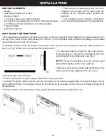
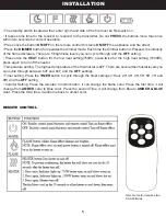
• This appliance is designed to be fixed to a wall at a minimum height of 300mm and the minimum distance from
the top of the heater to the ceiling should be 1000mm. The wall bracket must be fitted horizontally and the cable
routed to the bottom right of the heater.
• A distance of 600mm from the bottom of the heater to the floor is recommended for optimum viewing of the fuel
bed; see Fig.1 below for recommended fixing dimensions.
• For optimum viewing, mark the top four screws (
fixing positions on the wall in accordance with the
recommended fixing dimension; See Fig.2
NOTE
: Ensure the bracket is level by using a spirit
level whilst marking out the hole positions.
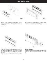
• Remove white screws on both side and Remove the
back panel from the appliance first, see Fig.2
• Drill holes with a No.6 drill bit.
• Fix the wall bracket using the plug and 4x30mm screws provided.
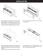
• Carefully lift up the heater ensuring the top rear ledge of the heater engages with the wall bracket(see Fig.2)
and is sitting centrally. This process should be carried out by two people to avoid injury or damage to property or
the appliance.
• Put the crys
tal to the white boarder, then gently bring the heater down against the wall.


