background image

OPERATION

11

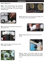
Step 7. 

Place the CFT cell into the piping and 

screw the unions back onto the ends of the 

new cell. Tighten the thread. The cell can be 

positioned either way. In fact, we suggest to 

reverse the cell every time you clean it to extend 

the life of the cell.

Step 8.

 Plug the power cord into the lower corner of 

the controller.

Step 9. 

Restart the pool pump and salt chlorine generator. The controller should light up and 

the pool pump should operate.

Step 10. 

Any air in the duct should be drained from 

the open safety valve. When the water begins to 

squirt from the safety valve, close the valve.

Step 11. 

After a couple of minutes, the controller 

display will show a salt value of between 2700 and 

3400 and the “Power” and “Generating” LEDs should 

be light on.

Summary of Contents for 90160

Page 1: ...ON MAINTENANCE AND CLEANING PROCEDURES WRITE THE PRODUCT S SERIAL NUMBER ON THE BACK OF THE MANUAL NEAR THE ASSEMBLY DIAGRAM OR MONTH AND YEAR OF PURCHASE IF PRODUCT HAS NO NUMBER OWNER S MANUAL AND SAFETY INSTRUCTIONS ITEM 90160 90161 90162 FOR QUESTIONS PLEASE CALL OUR CUSTOMER SUPPORT 909 628 0880 MON FRI 9AM TO 3PM PST ...

Page 2: ...lorine Output 6hr cell run time per day at 75 Congratulations on your purchase of a new T Series Replacement Cell Our cells are designed to meet or exceed original specifications for optimal performance and reliability T Cell 3 and T Cell 9 require software r1 5 for AquaRite or 4 2 for AquaLogic or newer to be compatible These revisions started in 2009 meant for use in Hayward Goldline AquaRite Aq...

Page 3: ...ressure at the relief valve it is usually on top of your pool filter Step 3 Unscrew the threads on both sides of the original T cell Step 4 Original AquaRite Turbo Cell out from the piping Step 5 Pull the plug out at the lower corner of the digital controller Step 6 Inspect the O rings inside the union connected with the pipe for any wear and replace them if possible Apply a thin layer of lubrican...

Page 4: ...the power cord into the lower corner of the controller Step 9 Restart the pool pump and salt chlorine generator The controller should light up and the pool pump should operate Step 10 Any air in the duct should be drained from the open safety valve When the water begins to squirt from the safety valve close the valve Step 11 After a couple of minutes the controller display will show a salt value o...

Page 5: ...PARTS LIST 12 1 THREAD 2 FLOW SWITCH ...

Page 6: ...TROUBLESHOOTING 4 ...

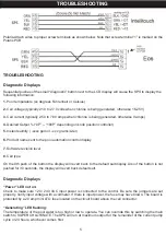
Page 7: ...e sent to the pool automation control display 7 Software revision level 8 Cell type On the 8th push of the button the display will revert back to the default salt display Also if the button is not pushed for 30 seconds the display will revert back default salt Diagnostic Displays Power LED not on Check to make sure 120 240 VAC input power is connected to the control Be sure the jumpers are set pro...

Page 8: ... STATES THAT ALL REPAIRS AND PARTS REPLACEMENTS SHOULD BE UNDERTAKEN BY CERTIFIEDAND LICENSED TECHNICIANS AND NOT BY THE BUYER THE BUYER ASSUMES ALL RISK AND LIABILITY ARISING OUT OF HIS OR HER REPAIRS TO THE ORIGINAL PRODUCT OR REPLACEMENT PARTS THERETO OR ARISING OUT OF HIS OR HER INSTALLATION OF REPLACEMENT PARTS THERETO Record Product s Serial Number Here Note If product has no serial number r...

Reviews: