background image

Xtreme Power Conversion Corporation

M90 User’s Manual

Page 35

Uninterruptible Power Supply


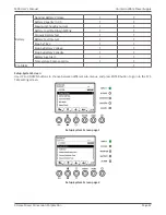
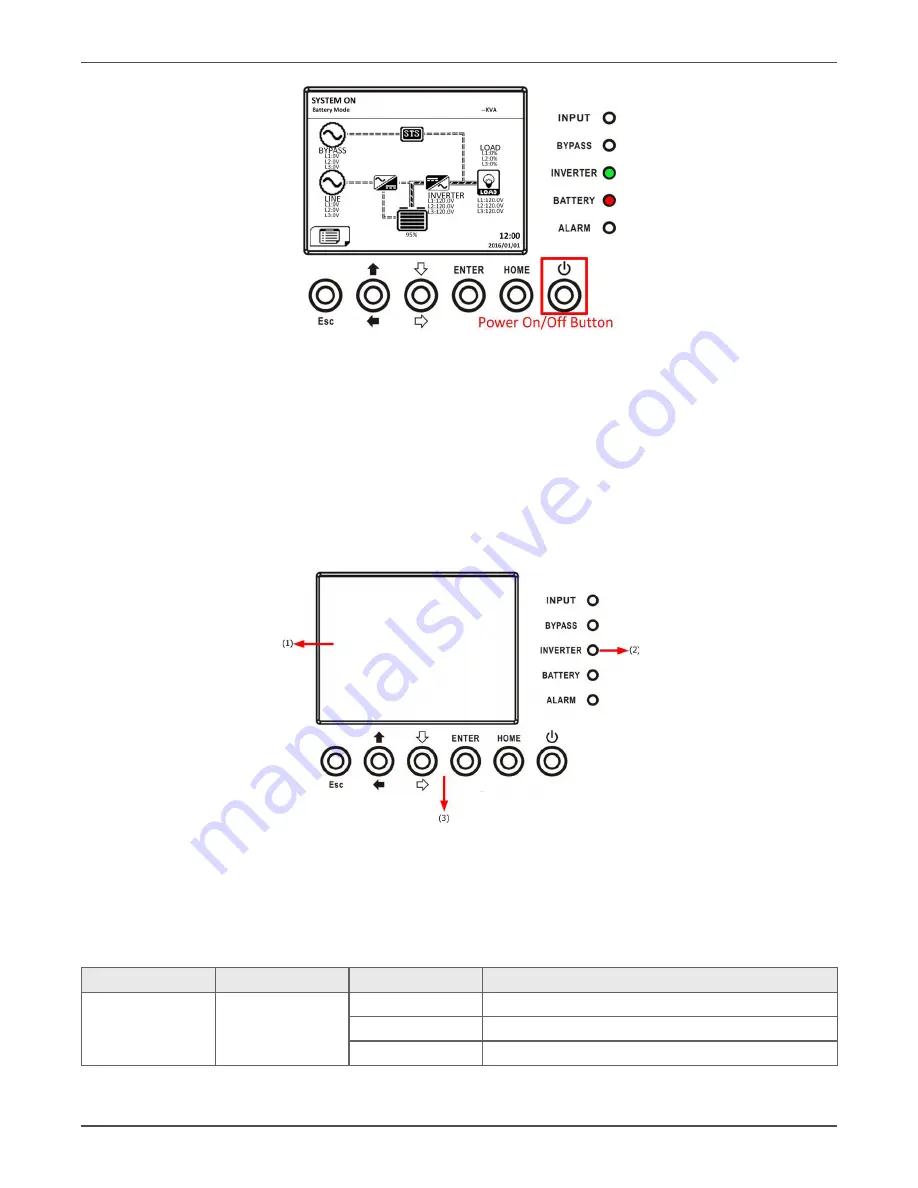
After turning off, the UPS will tranfer to Standby Mode.

Next, follow the 

Bypass Mode/ Standby Mode Turn Off Operation

 procedure.


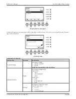
Control Panel and Display Description

Introduction

This control panel and display description are located at the front door of the UPS. It is the USER control, monitor

-

ing of all measured parameters, UPS and battery status and alarms. The control panel and display description are 

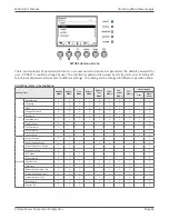
divided into four functional areas: (1) LCD display, (2) LED indications, (3) Control keys, (4) Audio Alarm.


Control panel

1. 

LCD display: Graphic display and all measured parameters.

2. 

LED indications.

3.  Control keys.

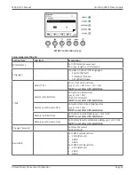
LED indications

LED

Color

Status

Definition

INPUT

Green

On

Input source is normal.

Flashing

Input source is abnormal.

Off

No input source

Summary of Contents for M90

Page 1: ...M90 M90L Modular Online Three Phase UPS 15kVA 20kVA 30kVA 40kVA 45kVA 60kVA Models User Installation Manual www xpcc com 2019 Xtreme Power Conversion Corporation All rights reserved Rev 1 8 19 ...

Page 2: ...n 5 Initial Inspection 5 Installation Environment 5 Unpacking 6 Moving the Cabinet 8 Types of UPS Cabinet 9 Exterior 9 Internal Mechanisms 13 Control Panel 14 LCD Display 14 IntroductionofModules 15 PowerCable 18 Wiring 18 Power Module Installation 20 Operation Mode and UPS Operation 23 Block Diagram of UPS 23 Operation Mode 23 UPS Operation 27 Control Panel and Display Description 35 Introduction...

Page 3: ...er Module 65 Specifications 65 Conformity and Standards 65 Environmental Characteristics 66 MechanicalCharacteristics 66 Electrical Characteristics Input Rectifier 66 Electrical Characteristics Intermediate DC Circuit 66 Electrical Characteristics Inverter Output 67 Electrical Characteristics Bypass Mains Input 67 Obtaining Service 69 Xtreme Power Conversion Limited Warranty 7 0Appendix A Battery ...

Page 4: ...dous Voltage between all terminals including the protective earth Risk of Voltage Backfeed The isolation device must be able to carry the UPS input current EMC WARNING This is a product for commercial and industrial application in the second environment installation restrictions or additional measures may be needed to prevent disturbances Installation Information WARNING Installation must be perfo...

Page 5: ...ains sealed lead acid batteries and must be disposed properly For more information contact your local recycling reuse or hazardous waste center Do not discard waste electrical or electronic equipment WEEE in the trash For proper disposal contact your local recycling reuse or hazardous waste center Installation Initial Inspection 1 Visually examine if there is any damage inside and outside of packa...

Page 6: ...om the front of the UPS and the external battery cabinets for maintenance and ventilation 8 For safety concerns we suggest that you shall Equip with CO2 or dry powder fire extinguishers near the installation area Install the UPS in an area where the walls floors and ceilings were constructed by fireproof materials 9 Do not allow unauthorized personnel to enter the installation area Assign specific...

Page 7: ...Manual Page 7 Uninterruptible Power Supply 1 2 3 3 Remove 2 fixing cabinet plates and loosen leveling feet by rotating them counterclockwise Then move the cabinet from the pallet 4 To fix the cabinet in position simply rotate leveling feet clockwise ...

Page 8: ...est that at least three people move the UPS to the installation area One person holds a lateral side of the UPS with hands another holds the other lateral side of the UPS with hands and the other person pushes the UPS either from the front side or from the back side to the installation area and avoid tipping the UPS 3 The casters are designed to move on level ground Do not move the UPS on an uneve...

Page 9: ...ocation Internal External Switch Unit 1 1 Max Power Module 3 20K 3 20K Exterior In the front of the UPS there are control interface LCD Panel communication slots communication ports and 3 Power Module slots All wiring terminal blocks are allocated in the back of cabinet The side panels are locked by screws The casters at the bottom of the UPS cabinet can be used to move over for short distances Th...

Page 10: ...e Power Conversion Corporation M90 User s Manual Page 10 Uninterruptible Power Supply Mechanical Data Dimensions UPS cabinet Width Depth Height M90 20 2756 39 370079 55 905512 M90L 20 2756 39 370079 30 03937 ...

Page 11: ...Xtreme Power Conversion Corporation M90 User s Manual Page 11 Uninterruptible Power Supply ...

Page 12: ...Power Module and control interface LCD Panel Rear View You will see the Main Maintenance Bypass Output and battery breakers which is installed on the bat tery cabinet Front View Rear View 1 LCD Panel 2 Control interface 3 Power module 4 Q3 output breaker 5 Q2 maintenance bypass breaker 6 Q1 main input breaker 7 Battery breaker M90 only ...

Page 13: ...ninterruptible Power Supply Internal Mechanisms Breakers At the rear of the cabinet you can see Main Maintenance Bypass Output breakers If the cabinet type is with the battery there is a battery breaker as well Rear View Output Maintenance Bypass and Input Breakers ...

Page 14: ... R S T and Neutral terminals 3 Main Input Block Connects main AC source Includes R S T and Neutral terminals 4 For UPS Grounding For UPS grounding Includes one grounding terminal 5 Battery Input Block Connects an external battery cabinet Includes Positive Negative and Neutral N terminals Rear View Wiring Terminal Block Control Panel LCD Display Through the graphic LCD display the user can easily u...

Page 15: ...UPS fault Flashing UPS alarm Off Normal Function Keys Control Key Description Esc When it is the Main screen you can enter menu by pressing ESC key Return to previous screen when screen is not in Main screen Return to previous value in the same row so you can change it For example when changing 4 digit password press Esc to allow cursor back to previous digit Up Left Key for menu page navigation o...

Page 16: ...ses forced convection cooling by these fans Cooling air enters the module through ventilation grills and exhalation exhausts through grills located at the rear of the module Please do not block the ventilation area 2 Ready Switch Unlock it before removing the Power Module Lock it when the Power Module is well installed Then the Power Module can start to work 3 DIP Switches There are three DIP swit...

Page 17: ...ss and the position of SW1 and SW2 the Power Module s ID is assigned These two switches SW1 SW2 are mounted in the Parallel board which is located at the back of UPS cabinet Parallel Board The SW1 and SW2 positions have been well installed before leaving factory It s not necessary to change it for single UPS system application Module ID Assignment SW1 SW2 Module Address Module ID SW1 SW2 Module Ad...

Page 18: ...urrent A 60 1 120 2 180 3 Power cable mm2 16 50 95 Fixation torque force lb in 20 20 20 Note Installer has to consider the max current and wiring gauge when considering future extension DC input maximum current and power cable configuration Model 20KVA 40KVA 60KVA Current A 98 196 294 Power cable mm2 25 95 150 Fixation torque force lb in 20 20 20 Wiring WARNING Before wiring make sure the AC input...

Page 19: ...urce connection This UPS is for Single input application connect Input1 to the AC power source and use 3 short wires to connect Input1 and Input2 Warning These three wires are required for Maintenance Bypass power source The sequence of three phase R S and T must be connected accordingly The wrong sequence will alarm a warning when the UPS is powered The N must be connected firmly A warning messag...

Page 20: ...nd maximum charging current in LCD setting Otherwise if battery setting is different from actual installation the UPS will keep warning Power Module Installation The weight of Power Module is over 30 kg so at least two persons are required for handling Insert the Power Module Warning The power Modules installed in the same cabinet must at the same rating 1 Adjust the DIP switch positions to set th...

Page 21: ...le Power Supply 2 Place the ready switch at the front panel of the module to the position i e in unready state 3 Insert the Power Module into an unoccupied slot by two persons 4 Secure the Power Module to the cabinet by fixing the screws at the front panel of the Power Module ...

Page 22: ...can support the critical loads At least one Power Module MUST stay in the UPS cabinet in case the UPS system is operating in Maintenance Bypass Mode 1 Turn the ready switch to the position 2 The Power Module FAULT LED RED indicator is lit to show the Power Module output is off and disconnected from UPS system 3 Use a screwdriver to remove the four screws from fixing holes 4 Two people pull out tog...

Page 23: ...PS Operation Block Diagram of UPS Wiring diagram Operation Mode This modular UPS is a three phase four wire on line double conversion and reverse transfer UPS that permits operation in the following modes Standby Mode Line Mode Battery Mode Bypass Mode ECO Mode Shutdown Mode Maintenance Bypass Mode manual bypass ...

Page 24: ...able set ting is Disabled and charger function will be active when the battery is present The load is not powered under this mode Standby Mode Diagram Line Mode In Line Mode the rectifier derives power from the utility power and supplies DC power to the inverter and the charger charges the battery The inverter filters the DC power and converts it into pure and stable AC power to the load Line Mode...

Page 25: ...e AC power to the load Battery Mode Diagram Bypass Mode Upon connecting to utility input power the UPS is in Bypass mode before UPS is turned on if BYPASS enable set ting is Enabled and charger function will be active when battery is present After UPS has been turned on if the UPS encounters abnormal situations over temperature overload etc the static transfer switch will perform as a transference...

Page 26: ... rectifier and inverter are working when the UPS is in ECO mode ECO Mode Diagram Maintenance Bypass Mode When the UPS is in the off state and the utility power source is absent the UPS will enter into shutdown mode Or when the UPS has discharged the battery to the cut off level the UPS will enter into shutdown mode as well When the UPS enters this mode it is going to shut off the control power of ...

Page 27: ...ake sure the Power Modules addresses have been configured Refer to the Power Module ID Assistance section Make sure the ready switch on the Power Module has been moved to the Locked position Make sure all the breakers are switch OFF AC Startup Ensure to follow this procedure when turning on the UPS from a fully powered down condition The operating procedures are as follows Step 1 Refer to the Inst...

Page 28: ...de is enabled Step 5 Make sure there is no warning or fault event happening If there is please refer to Chapter 6 Troubleshoot ing to solve it Step 6 Press Power ON OFF button for two seconds to enter into Line Mode as shown below After turned on UPS will do self test and start Inveter up UPS will be transferred to Line mode when all power modules are ready ...

Page 29: ...r Step 2 Press the Battery Start button on any one of Power Modules to start up the control power of all Power modules and STS as shown below Battery Start Button Step 3 After pressing the Battery Start button UPS will enter into Standby mode Refer to the diagram below for LCD display Step 4 Before UPS enters into shutdown mode please press Power On Off button for 2 seconds immediately as shown in...

Page 30: ...w Step 6 Switch ON the output breaker Q3 Cold start startup procedure is complete Maintenance Bypass Operation Follow the instruction to transfer to Maintenance Bypass and UPS protection as below Transfer to Maintenance Bypass Step 1 Remove the mechanical lock plate of Maintenance Bypass Breaker Step 2 Make sure the UPS operates in Bypass mode as shown below ...

Page 31: ...o change the PCBA of STS and Power Module Transfer to UPS Protection Step 1 Make sure the maintenance is complete The Power Modules have been installed well Step 2 Switch ON the Main Breaker Q1 as shown below Step 3 Please enter LCD SETUP MENU and choose SYSTEM to ensure that the Bypass mode is enabled If the Bypass mode is disabled you have to set it enabled Then exit the SETUP menu and check if ...

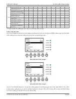
Page 32: ...plate as shown below Turn off Operation Bypass Mode Standby Mode Turn Off Operation When the UPS neither is turned on nor turned off the UPS operates in the Standby Mode or Bypass Mode It de pends on the Bypass Mode Setting The LCD diagrams are shown below Bypass Mode Setting is Disabled Bypass Mode Setting is Enabled Step 1 Switch OFF the Main Breaker The LCD diagrams are shown below ...

Page 33: ...hut off their control power Bypass Mode Setting is Enabled UPS stays in Bypass mode and No AC input is indicated Step 2 Switch OFF the external power switch to disconnect the AC power to the UPS Wait until the LCD is OFF Step 3 Switch OFF the battery breaker if the UPS will disconnect the AC power for a long time Line Mode Turn Off Operation The LCD diagrams are shown below when the UPS operates i...

Page 34: ... UPS After turned off the UPS will transfer to Standby Mode or Bypass Mode It depends on the Bypass Mode Setting Next follow the Bypass Mode Standby Mode Turn Off Operation procedure Battery Mode Turn Off Operation The LCD diagram is shown below when the UPS operates in the Battery Mode Press Power On Off button for 2 seconds to turn off the UPS Or use the Menu Control System Turn Off to turn off ...

Page 35: ...located at the front door of the UPS It is the USER control monitor ing of all measured parameters UPS and battery status and alarms The control panel and display description are divided into four functional areas 1 LCD display 2 LED indications 3 Control keys 4 Audio Alarm Control panel 1 LCD display Graphic display and all measured parameters 2 LED indications 3 Control keys LED indications LED ...

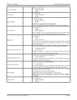
Page 36: ...pressing ESC key Return to previous screen when screen is not in Main screen Return to previous value in the same row so you can change it For example when changing 4 digit password press Esc to allow cursor back to previous digit Up Left Key for menu page navigation or digit modification Down Right Key for menu page navigation or digit modification Enter Confirmation of commands or cursor displac...

Page 37: ... Uninterruptible Power Supply Adjust the viewing angle of LCD panel Following the steps below you can adjust the LCD viewing angle Step 1 Remove the screw A Remove the screw A Step 2 Lift the panel and fix the screw back at B Lift the panel and fix the screw back ...

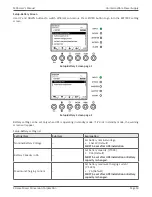
Page 38: ...display as shown below Main screen is divided into five parts 1 UPS Mode Current Operation Mode 2 UPS Flow Chart Current flow chart and measurement data 3 Menu Press ESC button to enter Menu screen 4 UPS model name with power rating If the power rating followed with R it means the UPS system is in redundant configuration 5 Date and Time Main screen MENU Screen In the Main Screen press ESC button t...

Page 39: ...n Corporation M90 User s Manual Page 39 Uninterruptible Power Supply Menu screen Control Screen Use UP and DOWN buttons to choose CONTROL option and press ENTER button to enter the submenu Control menu Control screen page 1 ...

Page 40: ...d by pressing ENTER button the confirmation screen will pop up Use LEFT and RIGHT buttons to choose YES or NO Choose YES and press ENTER button to confirm command or choose NO to cancel command Confirmation screen Measurement Screen Use UP and DOWN buttons to choose MEASUREMENT option and press ENTER button to go into the submenu Measurement menu ...

Page 41: ...asurement data Menu Item Explanation Input L N Voltage V Input phase voltage L1 L2 L3 Units 0 1V Frequency Hz Input Frequency L1 L2 L3 Units 0 1Hz Output L N Voltage V Output phase voltage L1 L2 L3 Units 0 1V L N Current A Output phase current L1 L2 L3 Units 0 1A Frequency Hz Output Frequency L1 L2 L3 Units 0 1Hz Power Factor Output Power Factor L1 L2 L3 Bypass L N Voltage V Bypass phase voltage L...

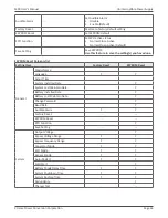
Page 42: ...mperature of extra communication card T1 Units 0 1 C Temperature3 C Battery cabinet temperature of extra communication card T2 Units 0 1 C Temperature4 C Battery cabinet temperature of extra communication card T3 Units 0 1 C Temperature5 C Battery cabinet temperature of extra communication card T4 Units 0 1 C Setup Screen Use UP and DOWN buttons to choose SETUP options It s required to enter passw...

Page 43: ...de Battery Test Mode Fault Mode Con verter Mode ECO Mode Authorization User Main tainer General Model Name Y Y Y Y Y Y Y Y Y Language Y Y Y Y Y Y Y Y Y Y TIME Y Y Y Y Y Y Y Y Y Change Password Y Y Y Y Y Y Y Y Y Y Baud Rate Y Y Y Y Y Y Y Y Y Y Audible Alarm Y Y Y Y Y Y Y Y Y Y Factory Reset Y Y EEPROM Reset Y Y EPO Function Y Y Save Setting Y Y Y Y System Output Voltage Y Y Y Bypass Voltage Range Y...

Page 44: ...Y Y Y Temperature Compensation Y Y Y Y Y Y Y Y Y Pre Alarm Y Y Y Y Y Y Y Y Y Y means that this setting item can be set in this operation mode Setup General Screen Use UP and DOWN buttons to choose between different sub menus and press ENTER button to go into the GEN ERAL setting screen General setting can be set in any operating mode Setup General Screen page 1 Setup General Screen page 2 Use LEFT...

Page 45: ...c MUST be set after UPS installation System Installed Date Set system installed date yyyy mm dd 2015 1 1 Default MUST be set after UPS installation System Last Maintain Date Set system latest maintenance date yyyy mm dd MUST be set after UPS installation Battery Installed Date Set battery installed date yyyy mm dd MUST be set after UPS installation Battery Last Maintain Date Set battery latest mai...

Page 46: ... done EEPROM Reset Category list Setting Item Factory Reset EEPROM Reset General Model Name Language Y Y Adjust Time System Installed Date Y System Last Maintain Date Y Battery Installed Date Y Battery Last Maintain Date Y Change Password Y Baud Rate Y Audible Alarm Y Y Factory Reset EEPROM Reset EPO Function Y Save Setting System Output Voltage Y Bypass Voltage Range Y Y Bypass Frequency Range Y ...

Page 47: ...own Setting Y Y Periodic Battery Test Y Y Battery Test Interval Y Y Stop by Time Y Y Stop by Battery Voltage Y Y Stop by Battery Capacity Y Y Battery Age Alert Y Y Temperature Compensation Y Y Pre Alarm Y Setup System Screen Use UP and DOWN buttons to choose between different sub menus and press ENTER button to go into the SYS TEM setting screen Setup System Screen page 1 Setup System Screen page ...

Page 48: ...t up in specific mode the warn ing screen will appear Warning screen Setup System setting list Setting Item Sub Item Explanation Output Voltage Set output voltage 120Vac Default 127Vac MUST be reviewed after UPS installation BYPASS SETTING Bypass Set bypass voltage range Upper limit 10 15 Default 20 Lower limit 10 20 Default 30 Voltage Set bypass Frequency range Upper Lower limit 1Hz 2Hz 4Hz Defau...

Page 49: ...utton Refer to cold start opera tion for the details Battery Mode Delay Time Set system shutdown delay time in battery mode 0 9990sec 0 Disable Default Not 0 Enable When this feature is enabled UPS will shut off output after UPS operates in Battery mode for certain seconds System Shutdown Time Set system shutdown time 0 2 99min 0 2 min Default This delay time will start counting when the CONTROL S...

Page 50: ...s operating in standby mode If it s not in standby mode the warning screen will appear Setup Battery setting list Setting Item Sub Item Explanation Nominal Battery Voltage Set battery nominal voltage 10x12V Default MUST be set after UPS installation Battery Capacity in Ah Set battery capacity 0 999 9Ah Default MUST be set after UPS installation or Battery capacity is changed Maximum Charging Curre...

Page 51: ...ys 30 Days Default Stop by Time Set testing time for battery test 10 1000sec 10 sec Default Stop by Battery Voltage Set stop battery voltage in battery test 11 12V x battery Number 11V x Battery Number Default Stop by Battery Capacity Set battery capacity to stop battery testing 20 50 20 Default Battery Age Alert Battery Age Alert Months Set battery age for replacement Disable 12 60Months Disable ...

Page 52: ... Lower limit 5 10 15 20 Default Line Frequency Range Set line frequency range Upper Lower limit 1Hz 2Hz 3Hz 4Hz Default Load Set UPS Overload percentage 40 100 100 Default Set UPS load unbalance percentage 20 100 100 Default Information Screen In INFORMATION menu you can check the serial number firmware versions system configuration and settings of the UPS There are submenus under the INFORMATION ...

Page 53: ...o and Firmware Version will be displayed Use UP and DOWN buttons to switch between different pages Identification screen page 1 Identification screen page 2 INFORMATION System Screen When System submenu is selected the system power nominal voltage nominal frequency etc information will be displayed Use UP and DOWN buttons to switch between different pages INFORMATION System screen page 1 ...

Page 54: ...ATION System screen page 2 INFORMATION System screen page 3 INFORMATION Battery Screen When Battery submenu is selected the Battery nominal voltage capacity charging current etc information will be displayed Use UP and DOWN buttons to switch between different pages INFORMATION Battery screen page 1 ...

Page 55: ...55 Uninterruptible Power Supply INFORMATION Battery screen page 2 Events Screen In EVENT menu you can check the current events history events and reset all events Events menu Events screen When event occurs you will see flashing warning text in the Main Screen ...

Page 56: ... press UP or DOWN button to read other events Current Events screen History Events The detailed event information is saved in history events It can save up to 500 events in history events When warning occurs it will display alarm code alarm time and Module ID When fault event occurs it will display alarm code alarm time Module ID and data 1 2 In order to record more historical information about th...

Page 57: ...Alarm List The table below provides the complete list of UPS alarm messages Alarm List Representation in display LCD Explanation Fault Bus Over Voltage DC bus voltage is too high Fault Bus Under Voltage DC bus voltage is too low Fault Bus Voltage Unbalance DC bus voltage is not balanced Fault Bus Short DC bus is short Fault Bus Soft Start Time Out The rectifiers can t start due to low DC bus volta...

Page 58: ...dequate space is allowed for air ventilation and the fan is working Fault CAN Fault CAN communication fault Fault TRIG0 Fault Synchronized trigger signal fault Fault Relay Fault Inverter relay fault Fault Line SCR Fail Line SCR short circuit fault Fault EEPROM Fault EEPROM operation error Fault Parallel Cable Loosen Fault As stated Fault DSP MCU Stop Communicate As stated Fault Bypass Temperature ...

Page 59: ...al Pre Alarm Over Load Output Load over range Pre Alarm Load Normal Output Load recovered to normal Pre Alarm Load Unbalance Output Load unbalance History Record Important setting changed Item No Description Item No Description 1 Setup Model Name 2 Setup Turn On Password 3 Setup Language 4 Setup Change Turn On Password 5 Setup Adjust Time 6 Setup Nominal Power Display 7 Setup System Installed Date...

Page 60: ...ault Mode 8 UPS Mode Converter Mode 9 UPS Mode ECO Mode 10 UPS Mode Shutdown Mode 11 UPS Mode Un Connection 12 Control execution Item No Description Item No Description 1 Control System Turn On 2 Control System Turn Off 3 Control Manual Battery Test 4 Control Cancel Battery Test 5 Control Turn To Bypass 6 Control Shutdown Restore 7 Control Cancel Shutdown 8 Control Charger Turn On 9 Control Charge...

Page 61: ...Name Position Description SCL X1 1 I C communication SCL Signal SDA X1 2 I C communication SDA Signal 3 0V X1 3 3V Power GND X1 4 GND X2 Remote EPO Input Port The UPS has an Emergency Power off EPO Function that can be operated by a remote contact assigned by the user Users can set the logic N C or N O of this EPO Function through LCD panel X2 is the remote EPO input port Remote EPO input port Des...

Page 62: ...sonnel Fault Bus Under Voltage DC bus voltage is too low Contact service personnel Fault Bus Voltage Unbalance DC bus voltage is not balanced Contact service personnel Fault Bus Short DC bus is short Contact service personnel Fault Bus Soft Start Time Out The rectifiers could not start due to low DC bus voltage within specified duration Turn off UPS and then restart the UPS If it fails again conta...

Page 63: ...service personnel Fault TRIG0 Fault Synchronized trigger signal fault Contact service personnel Fault Relay Fault Inverter relay fault Contact service personnel Fault Line SCR Fail Line SCR short circuit fault Contact service personnel Fault EEPROM Fault EEPROM operation error Contact service personnel Fault Parallel Cable Loosen Fault As stated Check if the parallel cable is loose and con tact se...

Page 64: ...l and contact service personnel Warning Internal Initial Fail As stated Contact service personnel Warning Comm Syn Signal Fail Communicate Synchronization Signal Fail Contact service personnel Warning Comm TRIG0 Fail Communicate Trigger signal fault Contact service personnel Warning Redundancy Set Fail As stated Check the redundancy setting is correct and contact service personnel Warning Parallel...

Page 65: ...l out together and remove the Power Module from its slot together 5 After servicing the module confirm that the DIP switch of the module is set correctly and the ready switch is in unready state 6 Push the module into the cabinet and tighten the screws on both sides If there are more than one power modules to re install please wait 30 second before installing another module 7 The re installed Powe...

Page 66: ...r kVA Unit 60 Dimensions W x D x H mm 515 x 1000 x 760 Weight kg 182 Color N A Black Protection degree IEC 60529 N A IP20 Electrical Characteristics Input Rectifier Rectifier AC input mains Rated power kVA Unit 20 60 Rated AC input voltage Vac 208 220 3 phase and sharing neutral with the bypass input Input voltage tolerance Vac 156 253 121 253 output derated below 70 Frequency Hz 50 60 tolerance 4...

Page 67: ...ty 170 Steady state voltage stability 1 balanced load 2 100 unbalanced load Total harmonic voltage 2 linear load 4 non linear load Synchronization window 1Hz 2Hz 4Hz default 4Hz Note Factory setting is 208V 220V is selected by commissioning engineer Electrical Characteristics Bypass Mains Input Rated power kVA Unit 20 60 Rated AC voltage1 Vac 208 220 Three phase four wire sharing neutral with the ...

Page 68: ...b SNMP Relay Modbus INCLUDED IN BOX User manual RS 232 cable Ramp for unloading UPS enclosure AVAILABLE OPTIONS External maintenance bypass 480V input transformer output distribution battery temperature sensor Specifications MODEL NUMBER M90L 20 M90L 40 M90L 60 CAPACITY Power Rating 20kVA 18kW 40kVA 36kW 60kVA 54kW Enclosure capacity power mod ules Up to 60kVA 3 x 20kVA INPUT Voltage frequency nom...

Page 69: ...ask you for the above information and if possible help solve your problem over the phone In the event that the unit requires factory service the technician will issue you a Return Mate rial Authorization number RMA If you are returning the UPS to Xtreme Power for service please follow these procedures 1 Pack the UPS in its original packaging If the original packaging is no longer available ask the...

Page 70: ... approved third party b the equipment is damaged by the customer is improperly used or stored is subjected to an adverse operating environment or is operated outside the limits of its electrical specifi cations or c the equipment has been used or stored in a manner contrary to the equipment s operating manual intended use or other written instructions Any technical advice furnished by XPC Corporat...

Page 71: ...Xtreme Power Conversion Corporation M90 User s Manual Page 71 Uninterruptible Power Supply Appendix A Battery Cabinet Installation Assembly ...

Page 72: ...Xtreme Power Conversion Corporation M90 User s Manual Page 72 Uninterruptible Power Supply ...

Page 73: ...Xtreme Power Conversion Corporation M90 User s Manual Page 73 Uninterruptible Power Supply ...

Page 74: ...Xtreme Power Conversion Corporation M90 User s Manual Page 74 Uninterruptible Power Supply Internal Battery Wiring DC 120V External Battery Wiring ...

Page 75: ...Xtreme Power Conversion Corporation M90 User s Manual Page 75 Uninterruptible Power Supply Note Ensure the UPS is properly grounded Battery Replacement ...

Page 76: ...Xtreme Power Conversion Corporation M90 User s Manual Page 76 Uninterruptible Power Supply ...

Page 77: ...Xtreme Power Conversion Corporation M90 User s Manual Page 77 Uninterruptible Power Supply ...

Reviews: