Ducts Application Note
VESDA-E
35424_02
1
1
VESDA-E System Design
Sampling Pipe Configuration in Small Ducts
1.1.1 VESDA-E VEP-1P
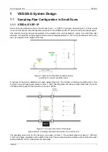
Small ducts are defined as those of width less than 1 m (3.28 ft). The figure below (Figure 1) shows a side
view of a duct section with the insertion positions for the VESDA-E VEP-1P detector inlet and exhaust pipes.
The detector inlet pipe should be installed in the middle of the duct at height H, where H is half of the duct
diameter. The detector exhaust pipe should be inserted approximately 0.5 m (1.64 ft) downstream of the inlet
pipe, at a quarter of the height of the duct.
Figure 1: Side view of the inlet and exhaust pipe
positions for a small ventilation duct.
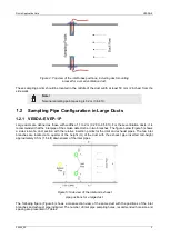
A top view of the above installation is shown below (Figure 2). The number of inlet pipe sampling holes, their
required size and spacing are listed in Table 1. Both sampling pipe and exhaust pipe holes have the same
orientation with respect to the direction of the duct airflow.
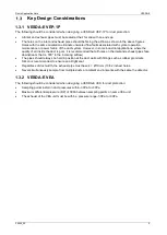
Figure 2: Top view of the inlet and exhaust
pipe positions, including sampling hole location, for a small duct.
The sampling hole sizes, for the inlet pipe, are shown in Table 1. The exhaust pipe must have 4 × Ø10 mm
(13/32 inch) holes, regardless of the width of the duct. These holes should be located in the middle of the duct
width at least 50 mm (2 inches) from the side walls.


