


Appendix BCompliance and Safety Information
FCC Radio Frequency Interference Statement
This equipment has been tested to comply with the limits for a computing device, pursuant to Part 15 of FCC rules.
These limits are designed to provide reasonable protection against harmful interference when the equipment is
operated in a commercial environment. This equipment can generate, use and radiate radio frequency energy and,
if not installed and used in accordance with the instructions, may cause harmful interference to radio
communications. However, there is no guarantee that interference will not occur in a particular installation. If this
equipment does cause harmful interference to radio or television reception, which can be determined by turning the
equipment off and on, the user is encouraged to try to correct the interference by taking one or more of the following
measures
1.Reorient or relocate the receiving antenna.
2.Increase the distance between the equipment and receiver.
3.The equipment and the receiver should be connected to outlets on separate circuits.
4.Consult the dealer or an experienced radio/television technician for help.
Changes or modifications not expressly approved by the party responsible for compliance could void the user’s
authority to operate the equipment.
If this telephone equipment causes harm to the telephone network, the telephone company will notify you in
advance that temporary discontinuance of service may be required. But if advance notice isn’t practical, the
telephone company will notify the customer as soon as possible. Also, you will be advised of your right to file a
complaint with the FCC if you believe it is necessary.
70
Summary of Contents for XL-VCF104M
Page 1: ...XL VCF104M CO XL VCF104S CPE VDSL2 CO CPE modem User s Guide...
Page 7: ...Figure 2 1 VDSL2 Point to Point application 6...
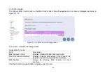
Page 20: ...6 1 1 Channel Configuration Figure 6 1 1 Channel Configuration Menu 19...
Page 23: ...6 1 3 Profile Configuration Figure 6 1 3 Profile Configuration 22...
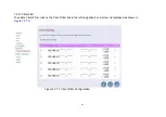
Page 24: ...6 1 4 Band Configuration Figure 6 1 4 Band Configuration 23...
Page 29: ...6 2 3 XTC Status Figure 6 2 3 Display of xTC Status 28...
Page 30: ...6 2 4 Version Info Figure 6 2 4 Display of Version Data 29...
Page 31: ...6 2 5 Graphs Figure 6 2 5 Display of SNR per Carrier 30...


