


Installation and Operation Manual
11
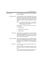
S-VHS In
NOTE:
Do
NOT connect both
S-VHS
IN
and
VCR IN
at
the
same time. The MUX-1602C will not function
properly with
both inputs connected.
Connect this input to the S-Video output (play) of an NTSC/EIA
(PAL/CCIR) compatible Super VHS video recorder. The
s-vhs
in
connector accepts S-Video from a Super VHS VCR.
S-VHS Out
NOTE:
Do
NOT connect both
S-VHS
OUT
and VCR
OUT
at
the same time. The MUX-1602C will not function
properly
with both outputs connected.
Connect this output to the S-Video input (record) of an
NTSC/EIA (PAL/CCIR) compatible Super VHS video recorder.
The
s-vhs out connector provides S-Video to a Super VHS VCR.
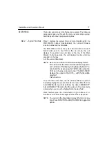
Alarm
The
alarm connector includes pins for mechanical or TTL/CMOS
standard Alarm Inputs, the Alarm Hold Input, and the Alarm
Output. These connections allow the MUX-1602C to be
completely
integrated with security systems. See
Alarm Response
for details.
Alarm Inputs
MUX-1602C Alarm Inputs accept a contact type or TTL/CMOS
alarm
signal. Connect
alarm pins 1 through 16, as required, to
one side
of a contact type or TTL/CMOS compatible alarm device.
Connect
the remaining side of each device to ground (alarm
pins 18, 19
or
20). MUX-1602C alarm input polarity is menu
selectable and defaults
to normally open (NO) or TTL/CMOS
active low.
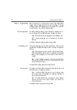
Alarm Hold Input
The Alarm Hold Input accepts an active high contact type or
TTL/CMOS alarm signal. Connect
alarm pin 22 to the alarm hold
output of the VCR or other device. Connect the remaining side
of the output to ground (alarm pins 18, 19 or 20). Not normally
used. See
Alarm Recording Control
for more information.
Alarm Output
The Alarm Output is a contact type signal between
alarm pin 24
(common) and either pin 23 (normally closed) or pin 25 (normally
open). Connect the appropriate pins to the alarm input of the
VCR or other device.


