76
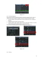
Figure 4-39
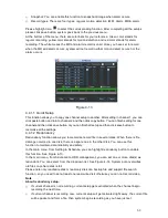
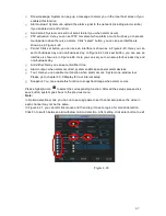
In Figure 4-36, click page switch button, the interface is shown as in Figure 4-40.
Here you can activate the following functions:
z
Preset
z
Tour
z
Pattern
z
Auto scan
z
Auto pan
z
Flip
z
Reset
z
Page switch
Figure 4-40
Note:
z
Preset, tour and pattern all need the value to be the control parameter. You can define it as
you require.
z
You need to refer to your speed dome
user’s manual for Aux definition. In some cases, it
can be used for special process.
z
The following setups are usually operated in the Figure 4-36, Figure 4-39 and Figure 4-40.
4.9.1Preset Setup
In Figure 4-36, use eight direction arrows to adjust camera to the proper position.
In Figure 4-39, click preset button and input preset number. The interface is shown as in Figure
4-41.
Now you can add this preset to one tour.
Summary of Contents for DVR-470
Page 1: ...1 DVR 470 870 1670 PK User s Manual...
Page 8: ...8 APPENDIX G EARTHING 175 APPENDIX H TOXIC OR HAZARDOUS MATERIALS OR ELEMENTS 180...
Page 32: ...32 2 3 3 2U series Please refer to Figure 2 10 for connection sample Figure 2 9...
Page 52: ...52 1U series 1 5U Series...
Page 53: ...53 2U Series Figure 3 11...
Page 68: ...68 Figure 4 21 Figure 4 22 Figure 4 23 4 5 3 Video Loss Figure 4 24...
Page 71: ...71 Figure 4 27 Figure 4 28 Figure 4 29 Figure 4 30...
Page 115: ...115 Figure 6 11...
Page 171: ...171 Samsung HA101UJ CE 1T SATA...

